


 Reply With Quote
couldn't figure out what these four connectors do
where they are located on the harness...
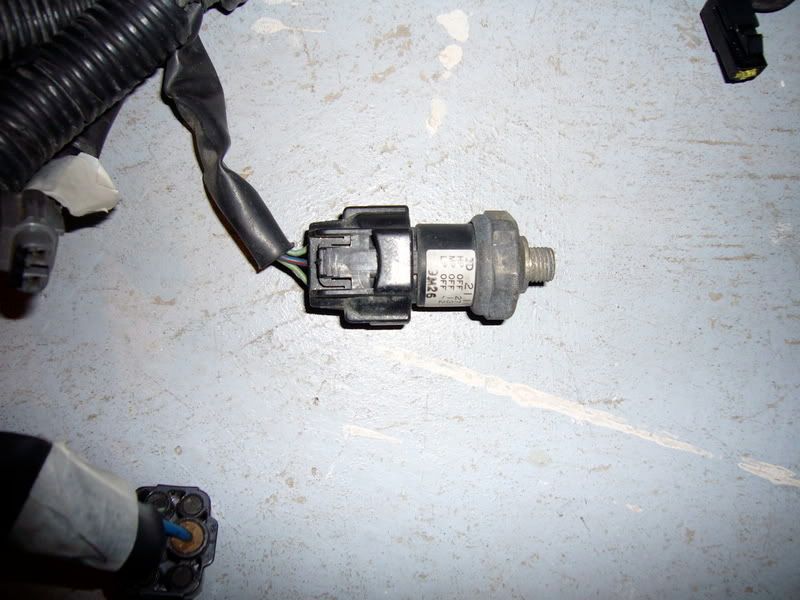
oh and one more thing, what is this for?
thanks again!
-Aaron


hey guys
long story short i bought an engine from an engine importer from ebay, got an AE101 4agze engine instead of an AW11 4agze and it came without a harness.
so i found an AE101 4agze harness for my aw11 swap, that came without a 22p connector to go into the ecu but found one that will work from an integra...anyways me and my mechanic buddy found some wiring diagrams (on this site thanks to The Witzl from this thread http://www.toymods.net/forums/showth...ht=ae101+4agze) and figured out which wires to splice except for a few. we couldn't figure out what each rely on the fuse box does. Also we were not sure if we would have to use the original MR2 fuse box or if we have to use the AE101 fusebox so if someone could point out which one we use and what to splice it would be much appreciatedalso the wiring harness came with 2 extra connectors (a 22p which does not fit in the ecu and a 20p which has all the wires that we need to splice into the 22p that i got from the ingtra to fit my ae101 ecu). me and my mechanic buddy were just wondering what they are there for and what function they're suppose to serve. finally we were wondering which wires will be needed to splice into the interior wiring harness of my 87 mr2 from the ae101 to make everything functional. we have done pinout tests in reference to the wiring diagrams provided. if anyone could tell us what we need to do to finish my swap up it would be much appreciated
. this swap has been a long time in the making and i would really like to get it done. thanks in advance!

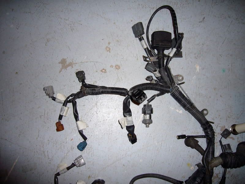
we also found some connectors that don't match up to the wiring diagrams that we have and could not figure out what their functions were either
couldn't figure out what these four connectors do
where they are located on the harness...
oh and one more thing, what is this for?
thanks again!
-Aaron
info like connector terminals that are not for the ecu are very hard to find
i have shitloads but dont give them out
buy a multimeter and do it the hard way like everyone else and find where the wires go
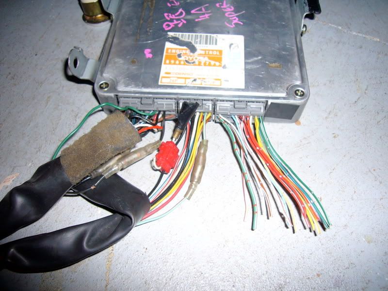
bottom pic is of air con reciever dryer pressure sensor
pic above it the brown and blue plugs are for the vac solenoids for the supercharger or pollution or fuel pressure reg
did the engine come with the vac lines and solenoids
anyway i think people are idiots buying stuff like that on ebay just to save afew bucks
so at end u get what you pay for but you get more headaches
anyway good luck and start probing
can i ask why you wouldnt give out information like that...? it would help me out a lot and i would greatly appreciate it
we have used a multimeter while referencing those wiring diagrams but even then some of the plugs did not seem to match up to any of the pinouts on the ecu plugs so we have a couple plugs that are unaccounted for. also when the wiring colors on the wiring diagrams dont really match up to our 22pin (the 16 and 26 pins are ok for the most part, just some locations are different) it gets really hard to know what we're looking at.
Since it is a JDM harness and we have no referance or complete TSRM to look at connector veiws, how can we be sure that the connector ends we are probing are right then?
I guess what Im trying to say is, we didnt do anything to save a few bucks. The harness was bloody expensive, the motor was rebuilt properly and we are trying not to cut any corners. The bottom line is that we got screwed over on the motor not getting the AW11 GZE and didnt realize it until it was too late. So we're trying to make up for it.
We're just a couple of guys who really do have a lot of time invested in trying to figure this out. Its our first swap, we're kinda new to this, not experts but motivated. We're not being lazy, we dont want a get out of jail free card, we dont want you to do this for us, we're just looking for a little insight to help us move forward.
Help a couple guys out, eh? Please?

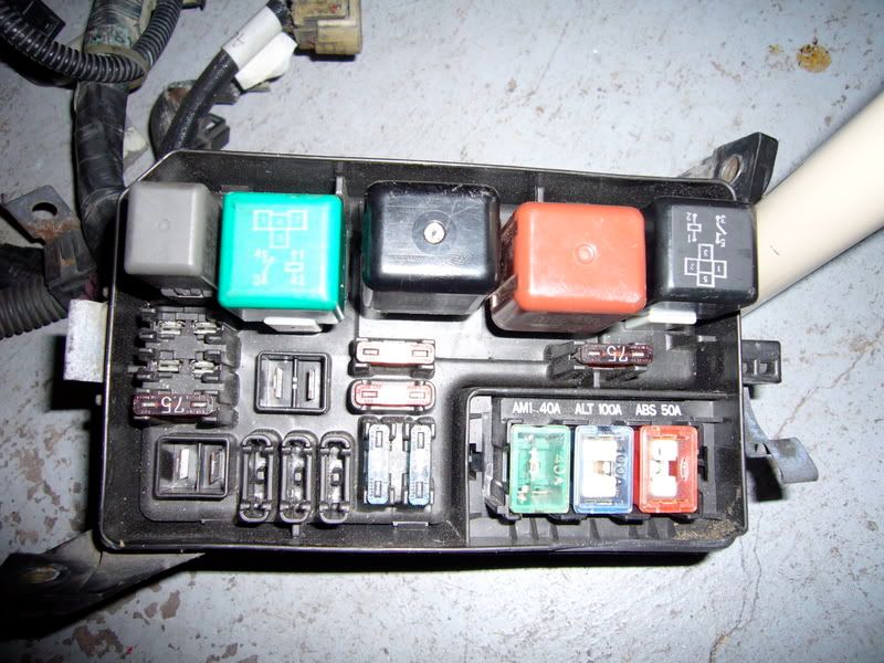
it's usually easier to use your original fusebox if the car was EFI to start with.
There's only a couple of wires from the fusebox that are engine related, like the EFI main relay output and +B feeds.
When you strip off all the tape and loom tube it's easy to figure out what's not engine related and discard it. In that loom you would have connectors for things like the fuel pump relay, supercharger relay, fuel pump resistor, injector resister, the brown and blue VSV (usually mounted on intake side of motor, on the timing cover side of the intake).
The last couple of looms I've had to do with no wiring diagrams available, I stripped all the tube and tape off the loom, applying rings of masking tape approx every 20cm along the loom and at the T's etc so it keeps it's shape. I then traced each wire individually and removed anything that wasn't engine related. With the leftover wires, it was fairly easy to identify the unknown wires which didn't go to the ECU plugs, usually things like:
-the water temp sender for the dash
-oil pressure sender for the dash guage or light
-starter feed (which T's to the ECU anyway)
-ignition feed
-main relay feed
-AC comp wire
-AC high pressure switch wire
-cooling fan thermoswitch wire
-Tach feed from ignitor
-Vc from the alternator to cabin charge light (alt wont charge without this connected)
-reverse light switch wires
-speedo sender wires (AE101 used an electronic speedo sender so has a 3 wire plug with wires you can get rid of, one of these wires splices in with one reverse light switch wire that has to stay) and a few others.
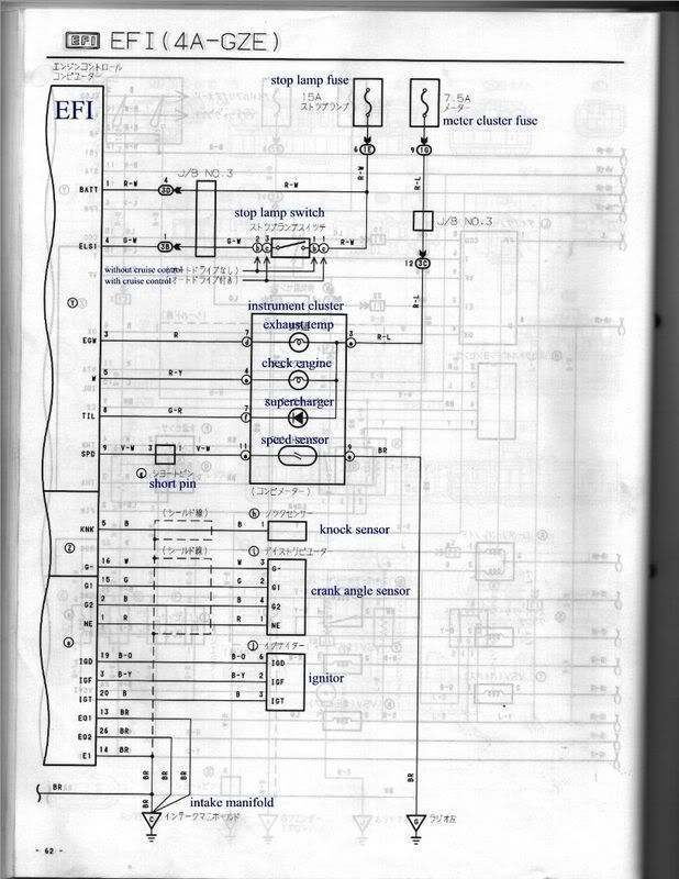
The AE101 ECU pinouts are fairly similar to the AE92 series III GZE, the CAS wiring is pinned differently but you dont need to touch that part of the loom anyway.
From your cutoff plug at the ECU, the main things you need to address are:
-power wires, both switched and constant
-the fuel circuit control wire
-stop lamp switch wire
-electrical load idle up wires
-supercharger led wire (dont need this)
-check engine light wire
-vehicle speed sense wire
Some more wiring info for MAP GZE's is available here: http://www.soniccreation.com/electrical_main.htm
If you're lucky the pinout of your ECU plugs will be screenprinted on the PCB next to each pin where it's soldered to the board. The last AE101 ECU I did was printed with the pinout. In that case you can remove the four screws from the top cover of the ECU and check the pins for that 3rd plug individually.
Get started on the loom and post up anything you get stuck with, some of us here are more than willing to help, I like to think that's the whole point of Toymods.
Jason
i dont cause im a c**t hehe
i help on these forums but i have to draw the line somewhere
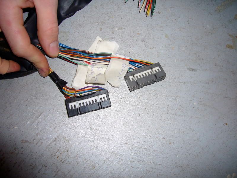
of those four connectors.....
blue = blue VSV
brown = brown VSV
i think the black one is the idle up valve (for aircon), and im not quite sure of the grey one off the top of my head.
Check out my uber vacuum diagram here for help... also do some searches for what ive posted before on "vacuum diagram"
http://www.18rg.com.au/tech/gze%20vacuum%20diagram.jpg
HEY HEY!!! I just found some pics in my files of the loom with those connectors connected to stuff...
enjoy!

...... butt scratcher?!
Hi guys,
For those who have posted information to aide us, thanks so muchWe realize we are a bit over our heads with this JDM motor and only half the parts, but progress can now be made again, even if in small increments
On the topic of injector resistors... seeing as our POS ebay GZE didnt come with a set, will we be ok using the stock 4AGE unit? If not, what about a substitute?
The major question of the day is this:
On the AE101 pinout diagrams we have http://www.skynet.ie/~eireae86/PETER_4A-GZE_ECU.htm the 26pin diagram is correct for pins 1-13 but is backwards for pins 14-26. For example, what is listed on the diagram as "Bottom Left of Plug Face" is actually "Bottom right of Plug Face". The wire colors are all there and all wires and pins are accounted for (via DVOM testing, lol) but the bottom row is just backwards.
So, here is my question... is this diagram actually correct, meaning our harness is wrong? I want to know because we have to re-pin the 20pin connector into our acura 22pin connector. We want to make sure that they are all going into the right spots, not half backwards. Our ECU part number matches that of the one in the above link.
ANy thoughts?
Thanks guys, much appreciated!
-Aaron
have you pulled the lid off the ECU to see if your circuit board is printed with the pin assignments next to each pin?
yea, we pulled the case apart to check the board but no luck there. I can only assume that either our harness has been tampered with or is wrong, or the diagrams are incorrect.
Ill crack open the box again when we get to the car this weekend and double check.
Thanks for the input!
-Aaron

That site is gold!!Originally Posted by JP
JP, I opened up the ECU again today and to my surprise, I found all the pin-outs printed right on the board, just as you described. Thanks! It definitely confirmed my suspicion that the pin out diagrams that I linked to above, are backwards for the bottom rows of pins on ALL 3 of the connectors.
WOOT!
Also, any idea about the injector resistors? Do you have any idea if we are safe using the 4AGE resistor block, or are we stuck having to find a GZE part?
Thanks again for the heads up on that...
-Aaron
well, more progress
But again, I have another question, this time regarding B+ wires and EFI main relay wires.
The AE101 GZE fuse box has four white B+ wires (3 large, one small) running off the box into the harness. There are also two more B+ wires running into the injector box/thing from a black 4 pin connector on the timing cover side.
The reason this is bothering me is because if we are to use the stock AW11 4AGE fuse box, we only have one B+ wire going into the harness from the fuse box. The GZE wires all seem to have continuity with each other (through the injector box I'm guessing) so does it really matter which wire I choose to use as my B+?
I think I got the EFI main relay all figured out too, so that is awesome!
Again, I really appreciate all the help you guys can offer. I'm by myself this week with no help, so I'm a little bit behind
THanks so much in advance,
-Aaron
Hi Aaron,
You can use your original B+ as the replacement feed for the GZE's B+ wires.
You can also use the GE resistor block in place of the GZE resistor block, if you don't have a set of the MAP sensored GZE injectors then you may find that someone from these forums has a set they're willing to sell (they're usually upgraded to 7mgte injectors when people go to a turbo setup.)
JP,
Ok then, easy as pie I guess
Now call me crazy, but looking at the 4AGE harness, there are only 4 wires that connect to the fuse box. B+, and 3 other small wires. Havnt had a chance to go through the AW11 diagrams yet, but that seems like an overly small amount to me... maybe I'm just crazy
Luckily, the engine DID come with MAP GZE injectors and what I believe to be the correct MAP sensor... whew!
Thanks for the info about the resistors... makes me feel better!
Much appreciated,
-Aaron
 Posting Permissions

Bookmarks