
 Reply With Quote
Yeah, dont force it in with the bolt.
It could quite possibly be the issue, you will have to check inside the hole to see if it would be an issue or not.


it feels solid. I thought that it would just be the oring because its not perfectly flush like the old dizzy, but im not sure
I tried a bit of motor oil on the shaft and around the oring but it wouldnt squeeze in. I tried tightening the bolt on that plate but I didnt wanna bend anything and it didnt seem to be doing it
Theres one difference in the shafts. If you look at the attached picture of the new distributer, that circled section of the shaft is the same all the way around
On the old distributor there's a small section maybe 20mm across on that section that is flat rather than curved.
I dont have it handy right now but I can put up a picture over the weekend.
I think that might be the problem, does that sound right?
cheers

Yeah, dont force it in with the bolt.
It could quite possibly be the issue, you will have to check inside the hole to see if it would be an issue or not.
1977 RA35 Celica GT - I4 | 2007 GSV40R Aurion - V6
Don't live life being scared of death, live in the fear of not truly living. RP 2012
hey hey...
well 4 months ago I kind of gave up on the electronic dizzy after I couldn't get it in. I recently made a thread over on rollaclub about my car. I mentioned the dizzy not fitting and taz pointed out that I just need to turn the engine over by hand slowly while the oil pump drive tang falls into place
anyway today with everything infront of me, it all made sense how to hook it up except for a couple little things.
* In the gregorys wiring diagram, it shows the black/yellow wire from the left of the ballast resistor goes to the fuse box.Originally Posted by RA35GT

* It also shows that red wire that's clipped directly to the coil as going straight to the ignition switch.
this is kinda confusing as I thought that the 12v comes from the ignition and then has to travel through the ballast resistor before getting to the coil, but the wiring diagram shows the red wire going straight from the ignition to the coil
1. is it the red wire or the black/yellow wire that goes onto the '15' spade terminal on the new module??
2. also there's 3 black wires coming off the coil as well. one goes to the ballast resistor, one goes to the coil's bracket (ground?) and the other from the negative goes along with the red wire somewhere that I can't figure out? the wiring diagram shows a black wire going to the distributor, but i thought that was the high tension lead...
3. so I should just hook the negative terminal on the new coil to the '16' terminal on the new module?4. If you have no tacho you dont have to do anything extra. Just tape up any wires that arent used anymore. (If you had a tacho it would be from the coil-)
thanks again... sorry about the dunce questions but my buddy who would help me out is overseas at the moment
The only stupid question is the one that isn't asked!
Onto your questions.
1. The wire that has black plastic connector on the ballast would be the 15 terminal wire. (Left hand side of the picture)
You can test this by using a multimeter or test light. It should have +12V with the ignition on.
The red wire that comes from the ignition (and connects directly to the coil +) may be the ballast bypass during starting. (I.e. the red wire only goes +12V during starting, once again this can be tested with a multimeter or test light).
2. The wire going to the ballast provides the power from ignition through the ballast to the coil.
The one that goes to the coil bracket is for the noise suppressor (the round can looking thing)
The other black wire from the coil negative is the wire which goes to the distributor and connects to the points.
3. Yes, that's right mate. Just connect pin 16 to the coil negative on the new coil.
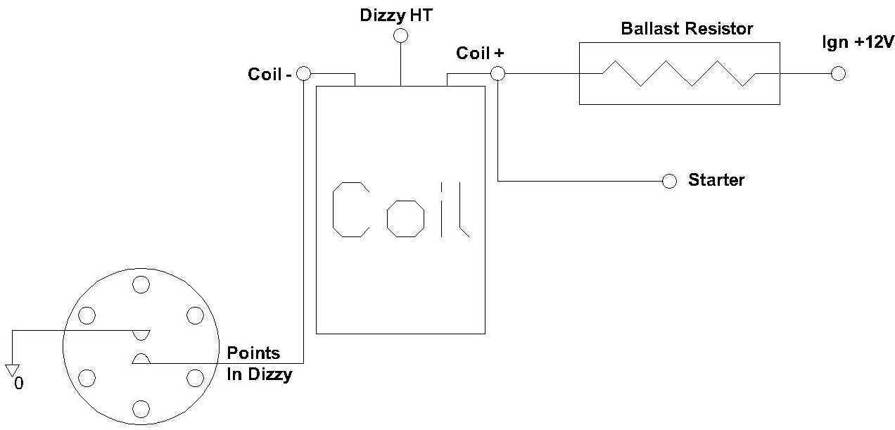
For your info, here is a generic points controlled spark setup with ballast.
Last edited by RA35GT; 11-10-2010 at 10:05 PM.
1977 RA35 Celica GT - I4 | 2007 GSV40R Aurion - V6
Don't live life being scared of death, live in the fear of not truly living. RP 2012
Ok great, all making sense now. thanks heaps
one last question before i give this a shot in the morning... does the new coil need the noise suppressor or do i ditch it??
thanks again
I'd keep it mate. Not for the coil, its so you don't get ignition noise through your radio/stereo.
1977 RA35 Celica GT - I4 | 2007 GSV40R Aurion - V6
Don't live life being scared of death, live in the fear of not truly living. RP 2012
ah yeah. would be helpful... particularly if I had a working radio/stereo
cheers mate, i'll let you know how it goes tomorrow
Hi,
Thanks heaps for this info, your Bosch Ignition Module convertion worked a treat in my RA65 with a 22RE. I killed my igniter by snooping too hardthen once it was stuffed as most would know I couldn't buy a new one
.
The salesman at Autopro said that he had a supplier that would use a generic Igniter Module and adapt it to fit for $300, but he wouldn't sell me the generic so I could adapt it, he probably didn't know the part to use.
Two things I like to add, is 1. reiterate the need for a "GOOD" earth, use Toyota's design philosophy, good engineering is good but over engineering is better. The other thing is attach the module to a "GOOD" heat sink, something that will take the heat away from the module. Like high wattage Stereo amps have big fins to radiate the heat away from their power Transisters, so should the Igniter Module. This could be the cause of the Bosch units 'supposed' lack of longevity. Alternaters die because they're too close to the Exhaust manifold especially on FWD cars.
Cheers again Jerry
update...
first of all it turns out it wasnt the tang at the bottom stopping the new distributor from going in, it was just the rubber o-ring. I swapped the o-rings over and it dropped in fine.
So anyway, i spent most of today wiring it all up. I mounted the coil in the old coil's bracket which worked well with a quick mod. I mounted the ignition module on the wheel arch as it should be a good ground and it gets it's ground through the bolt going into the body
anyway I really did think i had it all wired up correctly, but when I turn my engine on I get nothing... the engine is turning over, but there's no ignition....
however every 5 seconds or so is a fairly loud hollow knock sound...
I tried swapping the wires from the 3 and 7 terminals but no luck either
looking at the picture below, it should be all working right?? I know my wires are coloured differently but that's all my hardware shop had.
The thicker black cord at the bottom left is the one that was going into the left side of the ballast resistor, which then has a 'double adapter' kind of terminal on it which splits it to the positive of the coil, and the 15 terminal on the module.
the 16 terminal has a the yelllowy connector going straight to the negative on the coil (no tacho)
the other two are going to the dizzy connector but like i said i swapped them over too and no luck.
yeah i disconnected the HT lead to take the photo so don't worry it's not that
thanks
Your wiring looks right mate.
Make sure there is a full 12V on the coil+ and pin 15.
Just as a check, run a wire from a decent earth to the module bolt just to make sure its getting a decent earth and try starting it. (Did you grind away any paint on the other side of the panel for the washer/nut?)
How are you determining there's no ignition? (Take a coil lead off the dizzy and stick a screwdriver in it and place near an earth and check for a spark)
Also are you sure the dizzy is timed correctly?
1977 RA35 Celica GT - I4 | 2007 GSV40R Aurion - V6
Don't live life being scared of death, live in the fear of not truly living. RP 2012
lucas... 'lucas' .. LUCAS!!!! what you saying my man?? lucas is the crown lord of darkness.. we all know that especially in the classic british car / bike cogniscenti .. how can you teach pimp class with ho credentials?
Owner / operator of Souwester Marine . for all your boat maintenance needs. cleaning / detailing , polishing, paint, antifoul, fibreglass repairs / modifications (also for cars) .. I want an avatar!
update...
I hooked the coil/module straight to the battery just to test it out. I also timed the dizzy (best as I could without a timing light, but it would be pretty damn close)
still nothing...
gonna cost me $120 to get an auto-electrician out here and then an hourly rate to sort it out... he said I'd have to get it towed to him but when i told him it was a bosch 024 module he said he'd be happy to come have a look... he asked where each pin on it went and then said that seemed right so who knows
anyway it's a pain in the ass but hopefully this guy can just sort this shit out for me
Silly question I know, does the dizzy/rotor spin when the engine spins?
Pity your on the other side of aus, I'm sure it can't be anything serious as it does all look right.
Another thing, previously when I said timed correctly I meant in regards to the dizzy installation and camshaft/crank position. (I.e. to ensure the ignition fires on the compression stroke on the right cylinder).
1977 RA35 Celica GT - I4 | 2007 GSV40R Aurion - V6
Don't live life being scared of death, live in the fear of not truly living. RP 2012
Yeah the rotor turns when i crank the engine by hand...
and yeah with the timing, i dont have a timing light or compression gauge so i just stuck my thumb in the spark plug hole, then cranked until exactly where the air pressure turned to vaccuum... not the most accurate but quite close.
do you think you could explain how to test for spark again?? i tried googling it but didnt really get anything solid
i take a spark plug lead off the distributor cap, stick a screwdriver in, and then hold it close to an earth and a spark should fly from the screwdriver to the earth??
thanks
There should be a mark on the engine and the harmonic balancer to show top dead centre. (like a pointer type thing on the engine and a little notch taken out of the harmonic balancer) (may be slightly different position on a k engine but same principle)
as you bring the mark up put your finger over #1 cyl hole and it should go up in pressure. Then you know its nearing Top Dead Centre #1 Cylinder compression stroke. (If you feel no pressure you are nearing top dead centre #1 exhaust stroke, so turn the crank 360 degrees and you should then feel pressure). Then just line up the mark on the engine with the mark on the harmonic balancer. (they should be close already)
Re-install the dizzy, once installed there should be a mark on the dizzy that should line up with the rotor for #1 cyl. (The rotor will rotate as you push the dizzy in so you may need to put it in and out a few times to get it right).
To check for spark from the coil:
Take the HT lead off the distributor that comes from the coil. Stick a screwdriver into the end of the lead and place near an earth (i.e. approx 5-10mm, the engine block is good). crank for a few seconds and you should some sparks.
To check for spark from the distributor
Take a HT lead off a spark plug and stick a screw driver into the end of the lead and place near an earth, crank for say 10 seconds and you should see some sparks. (may need longer crank depending on where it is in cycle).
1977 RA35 Celica GT - I4 | 2007 GSV40R Aurion - V6
Don't live life being scared of death, live in the fear of not truly living. RP 2012
 Posting Permissions


Bookmarks