
 Reply With Quote
Good chance 21r/22r mounts from an RA6x will fit.


I forgot to ask earlier, with the mid mount points on a late model 18rgeu, the bolt spacing is a bit smaller, anyone know where to find the brackets or have some lying around? I can make some if need be was just I've never seen them mid mounted before.
Looking for a new toy. If you have something 18r powered let me know.
RIP, where ever you are :- 1974 celica, 3tgte and 186.5hp at 6500rpm
Good chance 21r/22r mounts from an RA6x will fit.
Cheers, Owen
1977 RA28 with 1JZ-GTE (Was 18R-GTE)
Lancer EVO Brakes into old Celica/Corolla/Corona
Doing the things that aren't popular... cause being popular and being good are often distinctly different.
Originally Posted by MarcusEstevez

dont you mean somebody paid you an 18RGUE to disspose of a shitty nissan part

Hi,
Got to agree. If you spent money with some professional mob to build your engine and they put in wrong parts or did it wrong, then you should be asking for your money back or for them to fix it at no more cost to yourself.
I bought my 18R-G, with full EFI (including the original ECU and wiring) for $300. Didn't bother starting it... and just took it straight to the engine builder. Builder mentioned the engine was in really good condition, so it would of started. Anyway, $1500 for a non-running 18R-G is a little rich, especially when you can get a running unit for less than half this. Of course, there will come a day when they are so rare they may command this price, but at the moment there's still plenty about if you look hard enough.
seeyuzz
river
The thinking man's clown and the drinking woman's sex symbol
RA25GT - There is no substitute | 18R-G - Toyota's Dependable Masterpiece
Toymods Car Club Treasurer, assistant Historic Plate Registrar & Forums Admin
yes river, mine were literally barn finds (more like old 2 side chicken coup) Engine A was sitting on the floor rusting is a true RG block with 9.5:1 pistons good guides & early head (although the head & block had been separated for some time). The bores were full of rust and dirt it was a major head fuck getting the pistons out without doing any damage. ive rescued them from the block but the comp rings are seized into the ring lands its proving a pain to remove them (currently soaking in diesel if anyone has a suggestion as to getting them out im all ears) upon inspection it appears this motor was given new mains and big ends only to fail again. there is damage to the leading edges of the dizzy drive gear (bad metal fragmentation) and some nasty scoring of some of the main bearings but the most of the bearings protective coating is still there. Eng B is still assembled (neither had any form of inlet gear hence cheapness) it is also an early head the valves are fucked i can see them its an old converted R block and appears to have been from a old hilux as it has the seldom seen super short engine mount bracket im yet to internally inspect it. grabbing the flywheel i can rotate it left to right a degree or two so its not entirely seized as the motors come from a sort of clued up guy im hoping internally it has hi-comp pistons and good oil pump and guides there are also 2 more RGs residing at this mans residence as well as a 2TG. Eng C the free one im yet to receive looks better in the pics ive been sent than the motors i paid for but has been sitting for 8 yearsits is however complete. in theory i now have 3 complete 18RGs and 2 spare ones (no manis or carbs to complete yet) and on the subject of price if i had a small windfall from whatever and i could spare $5k on a whim i would buy the HKS/TRD un-used race motor from USA since Peter Kipirios's (*SP) old meth inj drag RG is no longer avail.
I recently picked up a "running" geu with solexes only to discover bhg further investigation has revealed a couple bolts missing out of bottom end bearings haven't looked further as yet what damage should I be looking for
You should be looking for another 18R-G. Not having main caps bolted down? Serious levels of fail.
Anyway 18R-G friends, let's talk 18R-GEU wiring.
Let's have a serious talk.
Before I begin the process of getting lost in spaghetti (a.k.a making a wiring harness for my 18R-GEU), I wanted to make sure that I have a full comprehension of how all the components function so I don't have to go back and make changes. I have been using the two following images as my reference material (these have been re-hosted) -
Diagram -
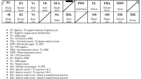
Pinouts -
(for those who need their specs)
IG - E1 - Vs - Vb - STA - x - PSW - TL - THA - THW - x
B+ - E2 - Vc - x - OX - IDL - x - #10 - #20 - E01 - E02
IG - Ignition - to negative side of the coil
E1 - Earth for O2 sensor shielded wire
Vs - AFM signal wire
Vb - 12v power for AFM
STA - cold start injector - to thermo switch in thermostat housing
PSW - full throttle signal - to TPS
TL - TPS negative
THA - air temperature signal - to AFM
THW - water temperature signal - to ECT
B+ - 12v power feed for ECU
E2 - Earth for AFM
Vc - AFM signal wire
Ox - 02 sensor signal wire
IDL - Throttle closed signal - to TPS
#10 - Injector circuit 1 - to injectors 1 + 2
#20 - Injector circuit 2 - to injectors 3 + 4
E01 - Injector earth circuit - attach to manifold near injectors
E02 - Injector earth circuit - attach to manifold near injectors
Okay. So here start my problems - mostly this is with differences between my two pieces of reference material -
My first problem is in the wiring diagram - the cold start injector, STA, thermo switch and 'auxiliary starter relay'
Okay. How the fuck does this work?! The cold-start thermoswitch earths through its body (?). One pin is provides the coldstart injector with an earth. Coldstart injector is powered by the STA wire (?) when the ECU sees low coolant temp (via ECT) (?). Aux start relay provides power to coldstart injector (teed with STA wire in the diagram?) under cranking conditions when the ECU would not normally power the STA wire (e.g. warm starts?). Backfeeding 12v to the ECU does not seem like a smart idea. And what's the deal with the other pin on the thermo switch that just appears to have a resistor illustrated within it?
And that auxiliary starter relay. It only has 3 wires going to it, 2 of which are grounds...
Second (smaller) question -
The Fuel pump relay on both it's 'load and 'control' sides has power at 'On / Crank' via the EFI relay. This is pretty clear. The 'control' side is earthed via the 'Fc' terminal on the air flow meter? correct? Am I to assume when the air flow meter receives power from the Main EFI relay, it provides the fuel pump relay with a ground? Seems like a very convoluted way to do it. That brings up another difference between the diagram and the pinout chart - there's a listing for an AFM 12v on the pinout chart, however the diagram has it with dedicated power from the main EFI relay. IIRC there are proven cases where a dodgy 12v feed to the AFM can cause issues and this is the reason for running a dedicated feed?
Third issue - Earths.
Okay. On this wiring diagram, there are multiple wires heading to terminal E1 on the ECU. Now I have (pretty reasonably) concluded this is the sensor ground terminal. Do ALL the sensors earth back to E1 as per the diagram? I.e. AFM, O2 sensor, ECT and the (not used) speed sensor? 3/4 wires converging to one terminal?
Injector control -
Conflicting information here. Diagram says injectors have B+ BATTERY power with a 2.5 ohm ballast resistor. Power at ALL times. That seems ridiculous. Also considering the pinout diagram describes terminals '#10' and '#20' as Injector circuits and 'E01' and 'E02' as injector earths, this leads me to the conclusion that I should negate the information in the diagram, the injectors are fired with a positive pulse from pins #10 and #20 (and have a constant ground) on the manifold, and that E01 and E02 should be used as ECU grounds.
Injector batching -
Again this seems odd. Even though it is a batch fire engine, it seems illogical to fire injector batches in a 1-2-2-1 sequence? (batches being cyl 1+2 on '1', 3+4 on '2', as listed in both the diagram AND the pinout) Would it not be better to fire them 1-2-1-2 and pair them 1+3 and 4+2? Anyone follow / care to weigh in?
IG-
This is just off the -ve side of the coil so the ECU has an RPM signal?
ALSO, the IACV isn't even mentioned on here..
Like I said, serious talk. When I have this all worked out I'll make a proper wiring diagram for this that can be used for all eternity.
Last edited by Javal; 19-02-2013 at 11:17 PM.
The 18R-G. The GOOD 2 Litre Tractor motor.
Have you seen this thread? http://www.toymods.org.au/forums/tec...w-dead%2A.html It has heaps of info also.
The cold start thermo switch is what provides the earth for the cold start injector. (Think of the cold start thermo switch as a relay whose positive trigger comes from a starter signal and negative triggers in cold conditions).
The cold start injector gets power from the start signal and its earth comes from the cold start thermo switch.
(Ignore the resistor in the cold start thermo switch, it's just a heater element so even in cold conditions after lots of cranking the cold start will stop injecting).
The aux start relay is not related to cold start. It's function is to trigger the fuel pump during cranking conditions when there isnt enough airflow to trigger the fuel pumps via the afm.
The STA terminal on the ECU is an INPUT to the ecu. The ecu uses it to see when you are trying to start the engine (i.e. the starter is engaged)
The afm controls the earth for the fuel pump relay yes. Not as soon as it is powered though. Fc is only earthed when there is airflow (i.e. the engine is turning/running) fuel pump will turn off when the engine stalls
The Vb pin on the AFM can either be a separate 12V to ignition +. Or if your ecu has a Vb pin labelled on it (open it up and check) connect the afm directly to the Vb pin on the ecu and nothing else.
Yes, all the E1's join together at the ecu. (all sensors earths must go to E1 at the ECU only) (Note that E1 and E2 are joined together internally to the ecu, but it is important to only ground one of these to a decent earth, this is to ensure the sensors and the ecu are operating at the same ground level).
(Note that the earth at the end of the afm plug goes to a chassis earth, it is what provides the earth for the Fc pin in the afm).
Power at all times to the injectors while ridiculous still works. I ran mine through a relay triggered by ignition however.
What you wrote about injector control is completely incorrect.
One side of the injectors gets ignition +12V.
#10 and #20 goes to the other side of the injectors. This is a switched negative trigger.
E01 and E02 are the grounds which the ecu uses to send to the injectors. (i.e. when the ecu wants to fire the injectors it will turn on the transistor which essentially connects E01 to #10, for example)
Probably much of a muchness with the injector batching, (not sure how often it triggers the injectors, either every spark trigger or otherwise) I imagine it would make bugger all difference at the end of the day in terms of economy/driveability with the factory ecu.
Yes, the IG is just off the coil negative. (make sure you use the factory 18rgeu coil and ignitor, I had issues using the 18rgu electronic ignition with it not revving properly. (also make sure it comes direct from the coil negative and not through a resistor, i.e. dont take it off the tacho feed).
There is no IACV as such. There is an auxilliary air valve. it just needs an earth and a ignition 12v. (it uses a bimetallic strip, ignition power causes it to heat the strip and gradually closes the air bypass as the engine warms up).
The latest version of the diagram I made. (although i just noticed i didnt document the earths correctly, on my car I have all the sensor earths going to E2 and then E1 on the ECU is earthed to chassis only)
Please ignore the colour coding in the above diagram, I had to make my own loom, so used my own colours.
Last edited by RA35GT; 20-02-2013 at 03:42 AM.
1977 RA35 Celica GT - I4 | 2007 GSV40R Aurion - V6
Don't live life being scared of death, live in the fear of not truly living. RP 2012
*edit: just got proved wrong, but I'll leave this bit*
The cold start system on a mechanically injected mercedes is much more logical (hell... it's german, they don't know another way). They have a 'thermo time switch'. Basically it measures the coolant temperature and triggers the cold start injector for a certain time (between 0.5 and 6 seconds) when you key on or crank the engine (I can't remember which).
RA35GT - That diagram of the cold start controller in the head looks scarily like a relay diagram (coil and switch in a box). That's what threw me off...
Tis a little confuzzling. It's meant to depict the resistive heat elements
Looks like this inside though.

1977 RA35 Celica GT - I4 | 2007 GSV40R Aurion - V6
Don't live life being scared of death, live in the fear of not truly living. RP 2012
In that case it's functionally identical to the thermo-time switch on the old mercs. While sitting the switch will be closed (injector on, but until it gets power from the other side nothing happens). When you go to crank the heater fires up and begins to heat the switch (to turn it off) and the injector opens. If you crank too long like this you've either flooded or have no spark and it eventually cuts the fuel when the strip gets too hot. And it turns off when you release the key (i.e. engine is running, normal EFI operational, no power to the injector).
I LIKE THAT PIC!
Woah. Rudi. That's everything I need. I think i owe you a cold one!
That said does anyone else have an opinion on the injector batching?
The 18R-G. The GOOD 2 Litre Tractor motor.
So you're sure it actually is a batch fire engine? The first injected commodore had wiring that looked like batch during too, but was simultaneous. They just did it because single injector drive (of the day) couldn't handle six injectors at once, so they split them
Yes matey.
The 18R-G. The GOOD 2 Litre Tractor motor.
I'm sure Toyota engineers spent ages working out the best combination.
I'd convert to a decent ecu with sequential injection.
1977 RA35 Celica GT - I4 | 2007 GSV40R Aurion - V6
Don't live life being scared of death, live in the fear of not truly living. RP 2012
 Posting Permissions


Bookmarks