Page 1 of 7 123 ... LastLast
Results 1 to 15 of 92

Thread: Dry-sump construction

  1. #1
    Junior Member Carport Converter Billzilla's Avatar
    Join Date
    Dec 2005
    Location
    QLD
    Posts
    1,427

    Default Dry-sump construction

    Thought I'd write a quick article on how to build a dry-sump system that doesn't cost heaps and is not too hard to make. Too many people either get it wrong or pay way to much for them, and that shouldn't happen.

    This is a rough schematic of how most systems look.


    You can see that there's a lot of oil lines running around the engine bay (seven) and that opens you up for excess weight in a racing car and also excess complexity and a greater chance of leaks and things going wrong.
    Fortunately, there's ways to reduce the number of oil lines and simplify things somewhat.
    With a little clever engineering, you can end up with this, or even a little more simple again.


    Three oil lines, and maybe even down to two. Having less oil lines also reduces cost, which is good for the car owner/builder.

    So here's how to do it ....
    Firstly, you don't need one of those expensive three-stage external oil pumps to move the oil around. They need Gilmer belts and so on to drive them, and while you may well still want to go that way you really only need a single-stage scavenge pump for most applications.
    You don't need an external pressure pump as the factory one that often sits at the front of the engine is good enough, again for virtually any application. All you have to do is change the oil feed into it from the sump to an external line. On something like the crank-mounted pump on a 4AGE it's pretty easy as they have a gallery already running up the side of the pump that you can tap into.
    Not the best photo, but this is what the oil feed to the pressure pump on my racing car looks like.


    There's a blanking plug on the side of the pump that you remove, and then attach a fitting for the oil line from the oil tank.

    What then normally happens on most dry-sump systems is that there's a remote oil filter fitting that has two oil lines, to & from, the big oil filter. With modern filters you don't really need to do that, so I'd recommend just leaving it on the side of the block as they come from the factory. However, what I'd recommend for a lot of cars that do club work (i.e. sprints of no more than say 10 minutes or so at a time) to fit a water-to-oil intercooler between the block and the filter. Pictured below is a Subaru WRX unit, and it's very easy to fit.


    All you need to do is to add two water lines, one from the cool pressure side of the water system and the return from the cooler to the hot water from the engine to the radiator. (For my new engine I am going to fabricate a small pair of alloy sleeves that go in the radiator hoses, one with a small scoop to get some of the cool water and the other a small venturi to help suck the water through the cooler back into the hot water return)

    Okay, so now the oil has gone through the engine and it's time to get it to the sump and then out and back to the tank.
    This is one of the cool bits of a dry-sump system, because the sump on such an engine is much more compact than a regular wet-sump one. They can be made 30mm deep on most engines, and that's a great help if you're tight for space. The other benefit of course is that even a good wet-sump will be very unreliable for getting oil to the pressure pump with lateral G's more than about 1.0 or so. All it takes is less than a second of no oil when cornering, and you've done thousands of dollars worth of damage - more than the cost of a dry-sump system!
    Fortunately it's not too hard to make one. The one below is the one we ehave made up for the SR16 that's going into the Mallock. It's about 30mm deep and it's made from a standard steel sump. The bottom is cut off and an angled plate is welded on to form a shallow V, running down in this case to the right side of the engine. That's important because most of the oil tends to end up on the right side of the sump, so that's often the best place to collect it.


    If you like, you can add scraper plates and so on to help get the oil off the crank. In this sump, we only have the single suction line, but a lot of people like two and there's nothing wrong with that, other than you typically need two scavenge pumps, one sucking from each end of the sump.
    Here's my Fraser's sump, and it has the oil collector running down the middle of the sump and two collectors.


    I can't see why you couldn't run a single scavenge pump with two collectors though.
    Also most important is to have a coarse steel mesh in the sum, to stop the odd bit of broken engine go through the scavenge pump and shred it. (Even so, if the engine goes BANG you have to very carefully inspect and clean every oil line thoroughly. More than one friend has destroyed a brand-new engine because of crud in the oil lines, left over from the last blow-up)
    Here's the current racing car's sump, with some off the mesh I was talking about.


    Also in that photo are a couple of magnets, to try to help pick up the little bits of metal that float around.


    From the sump, you then have to suck the oil out with a scavenge pump.
    This can be a little tricky, and is likely to be the most expensive part off the home-made system. Virtually all of them are belt driven by a toothed Gilmer belt and there's not a lot of ways around that. So this is the setup we have on the current racing car.


    As you can see, it's driven off the front of the alternator. That's a fairly easy way of doing it, though they are often setup to run on their own belt. They need an additional toothed pulley graften onto the front of the engine pulley, and that takes a little elegant engineering. No way around that unfortunately!
    The oil line from the sump comes out of the front of the sump and there's a short flexible line from there to the scavenge pump, then from the pump either (typically) through an air oil cooler or directly to the oil tank.
    The scavenge pump in that photo is one we made at home out of a chunk of alloy and two sets of Holden 308 oil pump gears, sitting end-to end. It's driven at about 2/3's engine speed. More on how fast to drive the pump shortly.
    An off-the-shelf alternative is one like this, from BDG in Perth.


    They're several hundred dollars but saves a lot of machining. (and oil leaks until you figure out how to make the damn seals work) Being a gear pump, they pump a lot of oil and so are a very good thing. Quick tip - try to orient the pump so that there is always some oil left in it, so the gears stay wet when they spin again, and so make suction. It's a pain in the arse having to prime the pump each time you want to start the engine otherwise.

    To work out how fast to drive the pump isn't too hard, all you need is a lathe os some other machine that has a constant speed output. You have to get the pressure pump from the engine and time how long it takes to fill a five litre container at such-and-such an rpm, then do the same with the scavenge pump. Then you run the scavenge pump so that it pumps 50% to 100% as much more as the pressure pump - The reason for that is the scavenged oil is full of air and very frothy, and so takes up a lot more volume. The scavenge pump, to do a good job, should also create a partial vacuum inside the engine so 100% more volume is just fine. The partial vacuum also helps increase power as it helps get the oil off the crank as it spins around.

    We came up with another solution that with a little patience and machining should work well - Mount the scavenge pump right on the front of the crank and spin it at engine speed. here's one we made for the Suzuki in the current racing car, and it has the troichoidal gears from two oil pumps in it, so it pumps exactly twice the oil as the pressure pump.


    There's a couple of small brackets that hold it to the front of the engine, and a small fitting attaches it to the front pulley. Thus we are able to lose the extra belt otherwise needed to drive the external scavenge pump. Also, if you make the steel line(s) that come up from the sump just right, all you need is a single clamp to hold them to the scavenge pump, thus again eliminating another one or two oil lines .... and so down to a total of two.

    From the scavenge pump, the oil then passes to the oil tank.
    Some time ago I drew up a rough diagram of how they're supposed to look and it'll do for now.

    Splitting this into two parts to get past the 10 image limit here.

  2. #2
    Junior Member Carport Converter Billzilla's Avatar
    Join Date
    Dec 2005
    Location
    QLD
    Posts
    1,427

    Default Re: Dry-sump construction


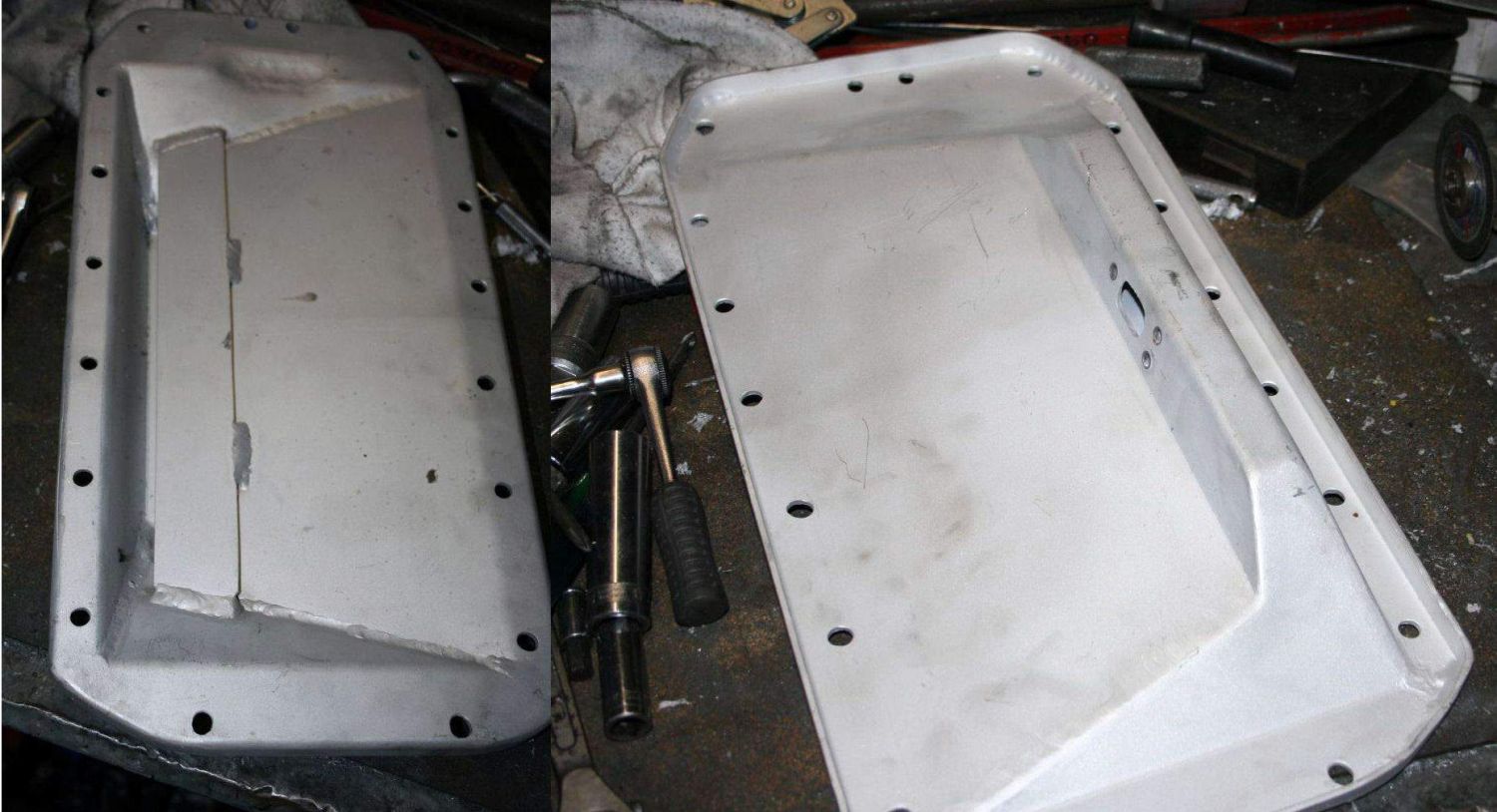
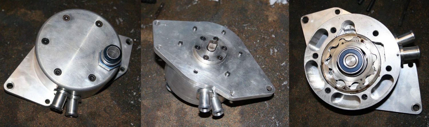
    #1 is the filler cap.
    #2 is the breather. It should go to a catch-can in case of overflow.
    #3 is the oil return from the scavenge pump. It comes in tangentially, to spin the oil around the inside of the tank to help de-airate it. Also cross-section 'A'.
    #4 is the plate that helps stop the oil swirling and fall down into the lower half. Also cross-section 'B'. Note the large hole in the centre, and smaller holes around the sides. It's also coned a little though this isn't too important.
    #5 is the oil line to the pressure pump.

    The oil level with the engine off should sit about 25mm below the plate. That level should be checked not long after the engine has stopped, as quite often oil will sneak back through the scavenge pump into the sump, so leaving the oil tank looking drier than it really is.
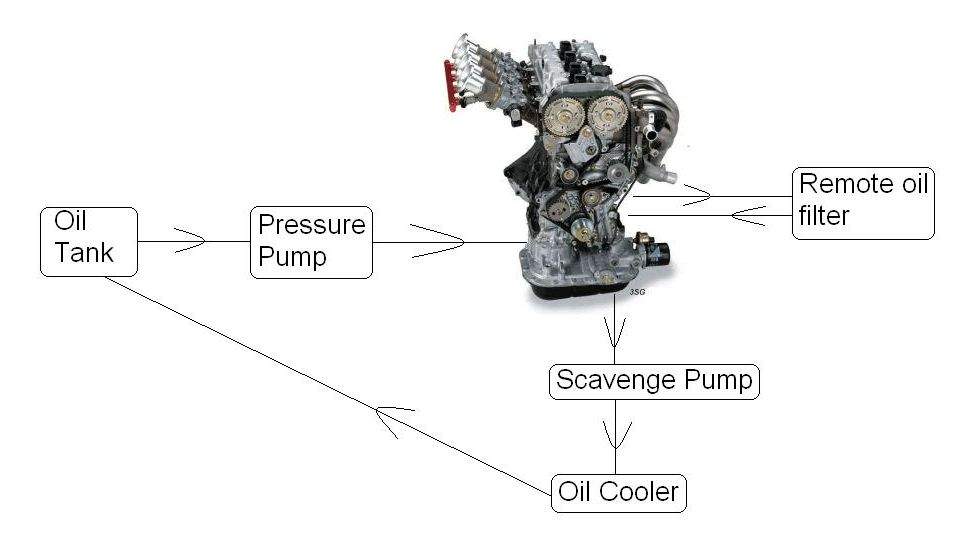
    There's no real minimum oil quantity with an oil tank, as long as is never comes close to running dry at high revs and there's enough running around for the oil cooler to work on. If the oil cooler isn't working well enough, no matter how much oil you have it'll eventually heat up too much.
    The really clever systems have the entire tank sitting inside the bell housing! But they're a lot harder to maching and keep cool.

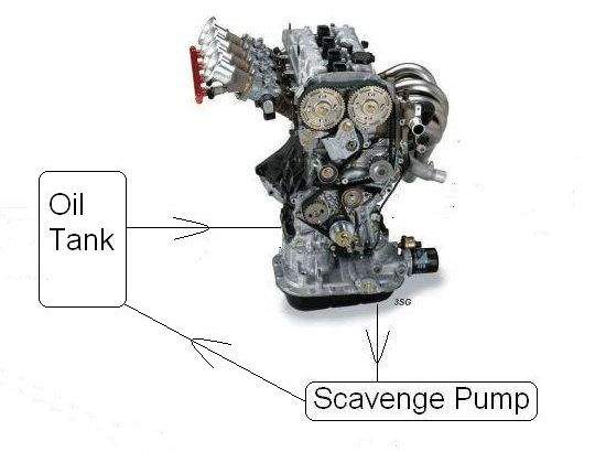
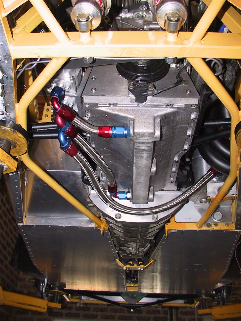
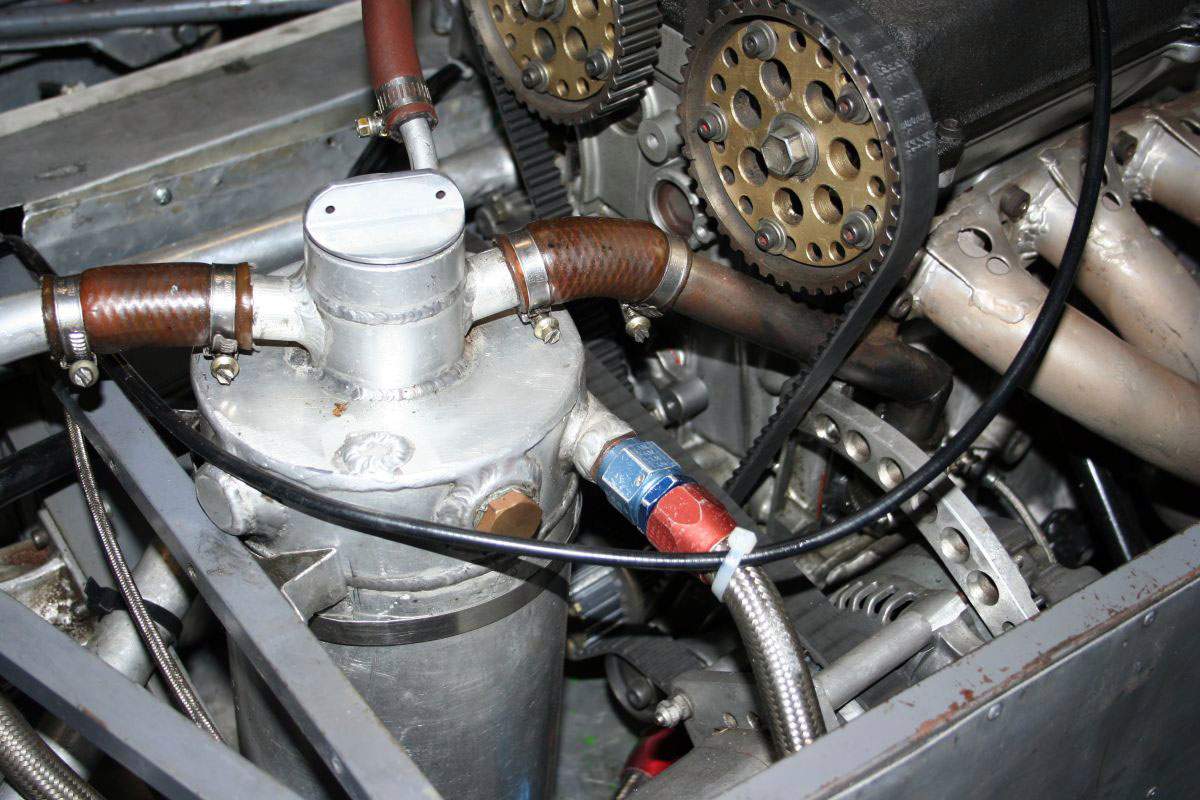
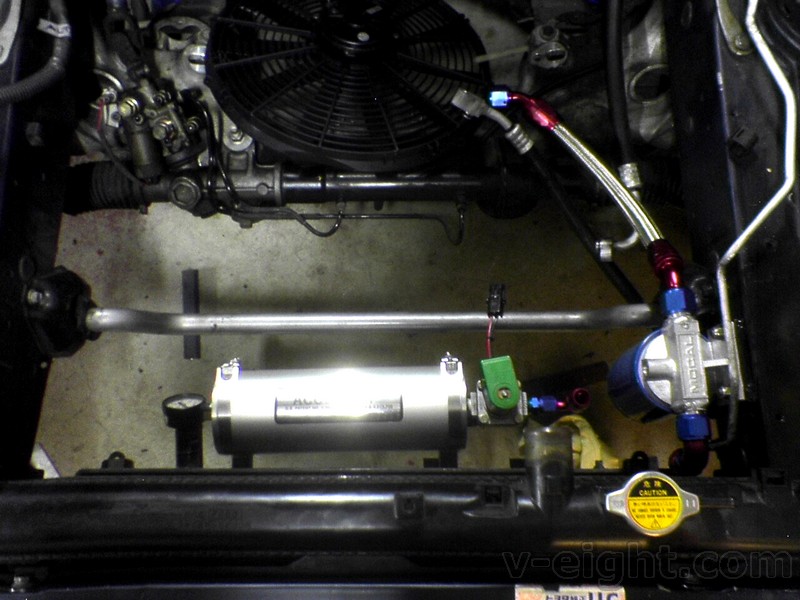
    Here's another photo of my racing car engine, and it's got a few things that aren't right.


    It's got a breather from the crankcase to the oil tank, and another from the cam cover. Those aren't needed, as the scavenge pump does all the breathing. On the new engine I'm building, it'll have a valve in the cam cover that maintains a preset vacuum in the engine. It's best to let the air in from the top, as the air will then travel from the top of the engine to the bottom, which helps the oil return from the head to the sump. The vacuum will be so good that for the twin-cam type engines that have the small semicircular rubber plugs in the back of the head, they have to be turned around so that the lip on one side is on the outside, or they will be sucked into the head.

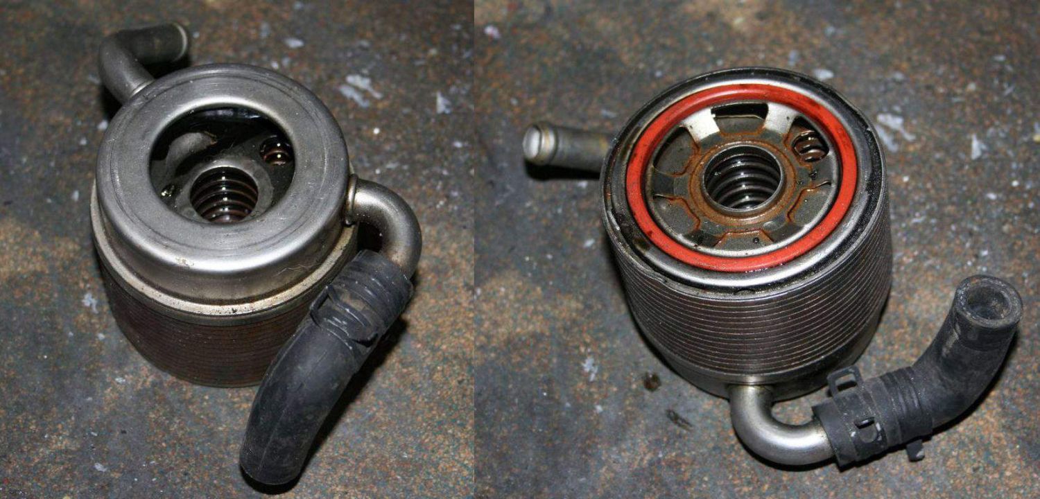
    Back to cooling the oil for a moment - A water-to-oil intercooler is a good thing for road cars and cars that only run for short-ish periods on the track. However, if the cooler is a good one (Setrab in-line type, etc) then they should be more than enough to do the job longer term. They also have the benefit of getting the oil warmer faster after startup, which helps reduce engine wear. The downside is that the water radiator must be able to shed the extra heat that has been added to it.
    If in doubt, a conventional air-type oil cooler will be fine, but make sure it get good airflow through it.

    That's all I can think of right now, more later maybe.

    Hope this is of interest.

  3. #3
    doctor ed Conversion King ed's Avatar
    Join Date
    Sep 2005
    Location
    Penrith BC
    Posts
    2,537

    Default Re: Dry-sump construction

    first up - good read there bill... + rep

    a few comments

    i figure dry sumps are good for a few reasons:
    1 increased oil capacity
    2 surge protection
    3 lower COG of engine
    4 ?less crankcase turbulence/friction from wetsump windage
    5 potential to generate neg crankcase pressure

    I gave dry sumping a good thinking before deciding against it in the supra/1uz. i ended up going the 'poor mans' dry sump - an accusump. heres a few reasons:

    toyota sumps and the engine x-member layout is already pretty trim in terms of lowering the engine pretty far down. the advantages of remaking a sump taht allowed the crank centreline to be lowered would be in the realm of 10-20mm max only.

    the oil tank required for a good dry sump is actually quite large. in a factory engine bay, finding space for such an area of free volume is pretty hard. the accusump I got is running around 2qrt functioning vol, is easy positioned in a low, out of the way place (lower COG again) and if you combine the rest of the circuit, theres quite a bit of added oil capacity to the system.

    the surge protection offered by this lasts well over several seconds, and buffers the system very well whilst the stock pump reprimes. It also overs pre-start oil prime.

    regarding windage, i figure half the battle is getting the free oil down into the belly of the sump, and keeping it there. if appropriately baffled, with use of good windage trays/scraper etc, whilst not as good as a truly dry sump, shouldnt be too bad.

    crankcase pressure is still an issue. but ive got to admit, i dont see a single stage scavange pump doing a whole lot for that either. ive not got anything to support that, but all the setups ive seen or read about run at least 2, usually 3, maybe 4 stages on the scavange side to really suck the case dry.

    i guess my gripe with a dry sump is cost, muliple stages where you have to watch for failure, and space. i feel theres limited benefit for 'most' factory/road cars even with sig mods, simply due to the restrictions placed by engine bay layout etc. the accusump is an alternative worth exploring in these situations. doesnt cover the whole story, i agree. neither does a poor mans single stage dry sump, but its all shades of grey along the continuum to a 6 stage speedflow bonanza!

    cheers
    ed
    ../delete/ban
    tech moderator
    E46 M3 Nürburgring Nordschleife - 8.38

  4. #4
    Gobble, Gobble! Automotive Encyclopaedia mrshin's Avatar
    Join Date
    Nov 2005
    Location
    Montrose
    Posts
    1,154

    Default Re: Dry-sump construction

    Good stuff, +rep for you.

  5. #5
    doctor ed Conversion King ed's Avatar
    Join Date
    Sep 2005
    Location
    Penrith BC
    Posts
    2,537

    Default Re: Dry-sump construction

    normal functioning conditions:


    following surge at the pump:


    ive got mine hooked up like this:

    wet sump -> oil pump -> 12an line -> remote filter -> (T line to accusump) -> full flow inline Setrab -> return to main oil gallery in block

    the accusump is the abs lowest part of the system, and can be seen sitting lower than the bottom edge of the radiator


    Last edited by ed; 29-11-2006 at 08:23 AM.
    ../delete/ban
    tech moderator
    E46 M3 Nürburgring Nordschleife - 8.38

  6. #6
    doctor ed Conversion King ed's Avatar
    Join Date
    Sep 2005
    Location
    Penrith BC
    Posts
    2,537

    Default Re: Dry-sump construction

    accusump introduction and installation instructions for anyone interested in reading more

    right click 'save as'
    http://www.racerpartswholesale.com/p...usumpinstr.pdf
    ../delete/ban
    tech moderator
    E46 M3 Nürburgring Nordschleife - 8.38

  7. #7
    Forum Member Grease Monkey
    Join Date
    Oct 2006
    Location
    sel
    Posts
    77

    Default Re: Dry-sump construction

    OMG... thanks billz... i was always wanted to build a dry sump for my 3SG...

    i have other things would like to consult u also... i couldnt get the ori fuel pump with no returning fuel line for my 3SGE BEAMS from SXE10... what is the suitable fuel pump to use?! which toy car fuel pump is competible with it?!

    thanks...

  8. #8
    back into it Chief Engine Builder
    Join Date
    Mar 2006
    Location
    nsw
    Posts
    3,991

    Default Re: Dry-sump construction

    Thought these might help!
    from http://www.aviaid.com/schems/scems.htm.

    4stage drysump system!


    3stage drysump system!


    2stage drysump system!


    single stage wetsump system!


    2stage wetsump system!

  9. #9
    tilting at windmills Carport Converter Ben Wilson's Avatar
    Join Date
    Sep 2005
    Location
    ACT
    Posts
    1,956

    Default Re: Dry-sump construction

    Bill, Can you resize some of your pictures?

    I'm viewing at 1600x1200 here and having to scroll left and right to read......
    Strange things are afoot at the circle K

  10. #10
    Nay sayer Domestic Engineer Mr Ed's Avatar
    Join Date
    May 2006
    Location
    ACT
    Posts
    624

    Default Re: Dry-sump construction

    Very nice work Bill, you make it all look so easy!!! I might go knock one up in my lunch break.

    +rep for you!

    Ed: The V8 super cars keep the oil tank in the boot to help weight distribution. (However I remember commentators stating that was the ONLY reason for a dry sump system )..........however this could also help your engine bay space issue should you eventually decide to go for full dry sump system.
    I used to eat alot of natural foods. That was until I learned that most people died of natural causes.

  11. #11
    Gobble, Gobble! Automotive Encyclopaedia mrshin's Avatar
    Join Date
    Nov 2005
    Location
    Montrose
    Posts
    1,154

    Default Re: Dry-sump construction

    Quote Originally Posted by Ben Wilson
    Bill, Can you resize some of your pictures?

    I'm viewing at 1600x1200 here and having to scroll left and right to read......
    Yah, I'm having the same issue at 1600x1200..

  12. #12
    back into it Chief Engine Builder
    Join Date
    Mar 2006
    Location
    nsw
    Posts
    3,991

    Default Re: Dry-sump construction

    Lol it is in no way the reason the v8supercars use drysumping! They run much bigger clearances to float the crank and use thick oil that has to be heated with 240volt heater before they race.
    Yes it does help the balance a little, but thats a tiny part of the reason.

    Bill we run mesh filters on the sump outlets aswell and epoxy mesh pieces into the heads oil returns to stop broken head gear getting down to the sump, metal and the alloy pump dont like each other
    Scavenge filters!


    System1 main mesh filter!


    You always change braided hose after a blowup, because the little bits of metal get stuck inside the hose

  13. #13
    Nay sayer Domestic Engineer Mr Ed's Avatar
    Join Date
    May 2006
    Location
    ACT
    Posts
    624

    Default Re: Dry-sump construction

    Just thought I might point out that I had a "" in that point about the V8s using it for weight distribution.

    Yes, I know they use it primarily for engine longetivity and have thought since theyve already got a tank, they may as well have it in the boot. This may also have been for quick access in pit stops.
    I used to eat alot of natural foods. That was until I learned that most people died of natural causes.

  14. #14
    back into it Chief Engine Builder
    Join Date
    Mar 2006
    Location
    nsw
    Posts
    3,991

    Default Re: Dry-sump construction

    No its just the best place to put it! Down low, rear passenger side of boot!

    Yes i saw the !

  15. #15
    Junior Member Carport Converter Billzilla's Avatar
    Join Date
    Dec 2005
    Location
    QLD
    Posts
    1,427

    Default Re: Dry-sump construction

    Okay ya bunch of small-screen girls, the photos are re-sized now.

    As Mick mentioned, a V8 Supercar just wouldn't run with a wet-sump engine, it'd crap itself around corners very quickly.

    Great schematics of the more complex systems as well, Mick, it shows how complex they can get.

Similar Threads

  1. Leaking Oil Sump Gasket on 4K ?
    By Tham in forum Tech and Conversions
    Replies: 1
    Last Post: 30-06-2006, 06:13 PM
  2. Sump position model guide (SPG#)
    By ed in forum Tech and Conversions
    Replies: 10
    Last Post: 31-01-2006, 02:15 PM

Bookmarks

Posting Permissions

  • You may not post new threads
  • You may not post replies
  • You may not post attachments
  • You may not edit your posts
  •