

 Reply With Quote
I know this is not vac related, how did u get the tps to clear the water pump and water lines?? Im making a blank tvis plate to then the t3 manifold to clear the water linrs, have u done the same??


Look at the stock 20v setup and repeat that?
KE30 4agte - Bullet - Rick Rolled
UZX83 1UZ W58- Cruiser - Tow Car - Fun Car
Originally Posted by -GT-

I know this is not vac related, how did u get the tps to clear the water pump and water lines?? Im making a blank tvis plate to then the t3 manifold to clear the water linrs, have u done the same??
No; sitting between the T3 Manifold and the TB's are ~ 15mm thick adapters I had made up (by SQ Engineering / see AE86 Driving Club Forums) to spin the TB's around 180Deg so that their orientation was @ factory. This was done for 2 reasons;
1. I wanted a Factory look for the Engine bay so wanted to be able to use a (modified) Factory S/T Plenum Box assembly. With the TBs right way-up, the OEM Plenum can locate on the dowels on the TBs
2. I wanted an accessible Throttle linkage; I think the T3 arrangement of running it u/neath the TBs is crap maintenance wise
Ah i get it now, i miss understood Sory bout that, thanks heaps mate!!
OK... I'm gonna give you my opinion on one item at a time, because you seem to
have a bunch of things all happening at once
1. ISCV
When you look at the factory ISCV you should be seeing something like a 12mm
tube on the airbox side, and something like a 15mm tube on the throttle side. This
valve supplies all the idle air to the engine on the factory setup. It does
this by passing air into the common vacuum rail, from which there are individual
connections of about 8mm to each throat in the intake manifold. The ISCV is active
whenever the engine is running, and the air passing thru the ISCV just becomes part
of the total combustion air at rpm's above idle.
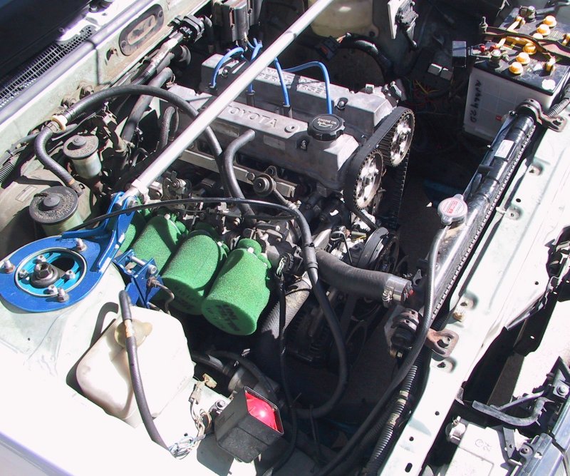
To duplicate the factory setup, I put an 8mm barb into the bottom of each runner
close to the head. These ran individually to a vacuum rail made out of an old fuel
rail. The rail connected to the ISCV thru a 2>1 tube arrangement. Here is a pic of
my engine...
Might look ugly, but it works a treatYou can't see it, but the line to the brake
booster comes off the end of this vacuum rail, and if you have P/S you would want
to take a line from this rail as well. All three of these items require flow, and due to
their irregular flow requirements, they will induce pressure fluctuations in the rail
whenever they operate.
Cheers... jondee86
Last edited by jondee86; 26-11-2011 at 07:44 PM. Reason: Pic didn't work :(
Now for everything else...
2. SENSORS
The little titties provided by Toyota on the throttle bodies are basically crap. The Fuel Pressure Regulator and MAP sensor require a fast responding, and smoothed vacuum signal for best engine performance. So, according to the collective wisdom of the interweb, it is best to take a separate tapping from each throat of your intake manifold.
Since the sensors respond to pressure changes, there is essentially zero flow in the sensor tubes. This means you can use small tubes (same size as factory) and the small tube will helping with damping unwanted signal pulsations. The tubes want to be as short as practical, and on the outlet side, incorporate a factory pulsation damper. On the inlet side, it is preferable, but not essential, to have the the tubes from each throttle run separately to a small vacuum collector.
From the above pic you will see I used the smallest barbs I could find, and located them close to the ITB's (upstream and separated from the ISCV barbs). The collector was made from a short piece of aluminum tube, about 20mm dia x 150mm long. The FPR and MAP sensor are connected to separate barbs on the collector.
This setup gives a razor sharp MAP signal response without any pulsation.
Cheers... jondee86
Last edited by jondee86; 26-11-2011 at 08:11 PM.
And now some "make it up as you go" theorising about manifold pressure...
3. VACUUM
There are a number of factors acting to lower manifold pressure at idle.
First, the ISCV is open, introducing air behind the closed butterflys... this will
drop the manifold pressure. But so does cracking the butterflys open to let idle
air into the engine, so probably unavoidable.
Here is my theory. On an ITB engine, each throttle makes vacuum in turn. That
means that at any given time, three throttles are able to either (a) leak air past
the butterfly, (b) leak air thru the factory bleed screw, or (c) lose vacuum by
sucking air from the ISCV collector/rail. The ISCV system acts as a balance pipe,
allowing air to transfer from the higher pressure throttles to the one active low
pressure throttle. This explains why you had a considerably better vacuum with
the ISCV system disconnected.
Trying to take a MAP signal from a single ITB will fail, as without proper
averaging, the signal will have heavy pulsation.
Compare this with the single throttle system that is the industry standard for
rule of thumb vacuum measurements. All the cylinders draw air from behind
a closed butterfly at idle. The inlet manifold acts as a balance chamber, but
there is much less chance for air leakage into the manifold. The idle air seems
to get in by way of butterfly leakage plus a tiny amount by way of the idle-up
port. Since the inlet manifold averages the vacuum from all four cylinders, it
makes a nice stable MAP signal.
Other causes of low vacuum are excessive valve overlap, bad timing, or
butterflys not closing fully (possibly why I have poor vacuum). However, as
I said previously, the ECU has the option of using a TPS only VE tune. This
factors MAP into the tune, and having used this tune for a few months, it
seems to work quite well
Cheers... jondee86
Last edited by jondee86; 22-12-2011 at 07:52 PM.
Hi there,
Thanks for all the info. To be honest I’m still scratching my head WRT a few things you mentioned which I’ll get to;. . . But I will say you’ve already done me a huge favour regarding using the OEM fuel rail as a Vacuum Canister; and by sharing your overall layout. I knew I needed to get the collector as close to the TBs as possible to replicate Factory layout but wasn’t sure how to do it - and the answer was staring me in the face.
ISCV:
Just to make sure we’re on the same page; what kind of inlet manifold are you running in your smallport? I can’t tell from the photo. I’m running a T3.
Following on from that; re. “I put an 8mm barb into the bottom of each runner close to the head.” Please clarify what you mean by “runner” i.e. did you tap Vacuum directly from u/side of each TB or (what I think you mean) from 4 outlets in the u/side of Inlet Manifold?
Where did you mount your ISCV? I can’t locate in the photo. I’ve mounted mine via 2 bolts; 1. Driveshaft Support Bearing bracket and 2. Adjacent vacant threaded hole. < photo attached >
Re. “The rail connected to the ISCV thru a 2>1 tube arrangement.” Could you please forward either a picture of the u/side of the rail or a schematic of that as I’m not sure what you’ve got going on as the TPS harness & various other electrical lines are obscuring the view. I.e. regarding 2>1; do you have another two 8mm outlets on the u/side of the “Vac.Rail” merging via a “Y” join into a 15mm Vac. Line that runs to ISCV?
Re. “The tubes want to be as short as practical, and on the outlet side, incorporate a factory pulsation damper.
1. By “tubes” you mean small dia. Vacuum hose; correct?
2. Re. “outlet side” not sure what you mean. On my AE111 only PD is the one just upstream of the MAP; there’s none in FPR line. Do you have any pictures of your layout (i.e. showing Pulsation Dampers)?
Re. “On the inlet side, . . . .small vacuum collector.” This is the 20mm tube, Correct?
Re. “if you have P/S you would want to take a line from this rail as well.” I was looking at the ISC article in the Toyota Autoshop101 manual < http://www.autoshop101.com/forms/h26.pdf >and one thing that threw me was the diagram on P6; showing throttle-side outlet running direct to P/S Idle Up Control Valve? I don’t get it.
What if you also have A/C? I do and according to P6 of the Toyota Autoshop101 manual < http://www.autoshop101.com/forms/h26.pdf > I’m going to have to re-insert the AE92 A/C Idle Up contraption so I’m going to have to plumb that thing into the mix as well. Would I merge those lines & run to this rail as well?
Lastly; how did you mount the “Fuel Vac. Rail” to the ITBs?
SENSORS:
Re. “Little Titties . . are crap”. I’m running a 3mm Vac Line from Dashpot to "Little Titty" on ITB#1; should I be running this off the “Fuel Rail Vac.” as well?
Re. “. . . it is best to take a separate tapping from each throat of your intake manifold.” OK, so I take it this means you have 8 ports in your Intake Manifold; 4 small for MAP & FPR. / 4 large for ISCV?
RE. “Located them (MAP/FPR Barbs) close to the ITB's (upstream and separated from the ISCV barbs. OK, I assume you tap the 2 sets of Barbs into the u/side of T3 Inlet Manifold, and that the two sets of Barbs would be offset both laterally / longitudonally from each other?
How did you mount the 20mm “Vac.Tube” to the ITBs / Manifold? Any pictures?
Cheers, GeeEss
Last edited by GeeEss; 28-11-2011 at 05:25 PM.
I have a custom tube manifold. Both my ISCV and sensor tappings are directly into the tubes (nothing from the ITB's).
Found a threaded hole down low by cylinder #4. Got one 8mm bolt holding it on.Where did you mount your ISCV? I cant locate in the photo. Ive mounted mine via 2 bolts; 1. Driveshaft Support Bearing bracket and 2. Adjacent vacant threaded hole. < photo attached >
Correct. You can see them in the pic... two 90 deg elbows and a 9x9x12 Tee joiner. Irrigation fittings and a bit of clear plastic tube.Re. The rail connected to the ISCV thru a 2>1 tube arrangement. Could you please forward either a picture of the u/side of the rail or a schematic of that as Im not sure what youve got going on as the TPS harness & various other electrical lines are obscuring the view. I.e. regarding 2>1; do you have another two 8mm outlets on the u/side of the Vac.Rail merging via a Y join into a 15mm Vac. Line that runs to ISCV?
Correct. Small rubber hoses. Outlet from collector to MAP sensor. I used a 20V pulsation damper, but you can find similar in-line dampers on a lot of cars in the junkyard. I wouldn't bother putting one in the FPR hose.Re. The tubes want to be as short as practical, and on the outlet side, incorporate a factory pulsation damper.
1. By tubes youre referring to small dia. Vac hose rather than actual metal tubes; correct?
2. Re. outlet side not sure what you mean. On my AE111 only PD is the one just upstream of the MAP; theres none in FPR line. Do you have any pictures of your layout (i.e. showing Pulsation Dampers)?
Correct.Re. On the inlet side, . . . .small vacuum collector. This is the 20mm tube Correct?
That diagram just shows an air inlet for the P/S that just happens to be tapped off the ISCV. The air to the P/S does not pass thru the ISCV, nor is it controlled by the ISCV. But the P/S air does finish up inside the intake manifold via the same route as air passing the ISCV. That is, it operates in parallel with the ISCV.Re. if you have P/S you would want to take a line from this rail as well. I was looking at the ISC article in the Toyota Autoshop101 manual < http://www.autoshop101.com/forms/h26.pdf >and one thing that threw me was the diagram on P6; showing throttle-side outlet running direct to P/S Idle Up Control Valve? I dont get it.
As far as I know, the 20V uses the ISCV to compensate for the A/C load. In any event, there is a setting in WARI under the "Idle" tab to raise the idle by a fixed amount to compensate for the A/C load. You just need to provide an input to the ECU so that it knows the A/C clutch has engaged.What if you also have A/C? I do and according to P6 of the Toyota Autoshop101 manual < http://www.autoshop101.com/forms/h26.pdf > Im going to have to re-insert the AE92 A/C Idle Up contraption so Im going to have to plumb that thing into the mix as well. Would I merge those lines & run to this rail as well?
There was quite some messing around involved. I had to handcraft a bracket out of a piece of aluminum angle, with holes in one leg to attach to the rail, and holes in the other leg that picked up existing threaded holes in the ITB's. I ran a tap thru the injector holes in the rail, and drilled a couple of new holes for the ISCV connections.Lastly; how did you mount the Fuel Vac. Rail to the ITBs?
That comment was maily aimed at the straight titties underneath each ITB. The two on top actually work OK. I'm not 100% clear on the function of the dashpot, and consequently, removed it entirely. Yours should work fine as it is.SENSORS:
Re. Little Titties . . are crap. Im running a 3mm Vac Line from Dashpot to Little Titty on ITB#1; should I be running this off the Fuel Rail Vac. as well?
Correct.Re. . . . it is best to take a separate tapping from each throat of your intake manifold. OK, so does this means you have 8 ports in your Intake Manifold; 4 small for MAP & FPR. / 4 large for ISCV
Theoretically, the barbs could be right next to each other. I just separated them because I couldRE. Located them (MAP/FPR Barbs) close to the ITB's (upstream and separated from the ISCV barbs. Can I tap both sets of Barbs into my Inlet Manifold? I.e. with the two sets of Barbs would be offset both laterally / longitudonally from each other?Main thing to watch is that you can still get in to tighten the manifold bolts with the barbs in place. Came very close to being a problem for me !!
Zip tied to the rubber hoses for the ISCV tappings.How did you mount the 20mm Vac.Tube to the ITBs / Manifold? Any pictures?
By the way, I don't claim to be any kind of expert on these things. I just know what worked for me, and I did put in a fair amount of research beforehand. No doubt there are many other setups that work just as well, and look prettier
Cheers... jondee86
This is all gold, il b doin the swap soon, but im using blactop itbs... This will help me heaps!! U guys rock!!
Thanks Jondee; I think I have enough info to get me out of trouble < or into more trouble? >. I'll let you know how I go.
Cheers; GeeEss
Forget the MAP sensing for quad-throttles, use Throttle Position Vs Revs, it works fine if you take a little time to tune it properly. I did that with my last 4AG about ten years ago ->
Drove perfectly well at small throttle settings and get very good fuel economy as well. I had to add a few load points at low throttle settings though. (Motec M4)
www.billzilla.org
Toymods founding member #3
Or if your ECU has it, ITB mode (Alpha-N / Speed Density blending).
I've just started to play with this feature on my MegaSquirt setup with my 20V and so far it seems to work good.
I agree completely, I am using the same TPS + the usual water + air temp correction and I have great fuel economy and driveability
I forgot to mention that the brake booster vacuum source on that engine was the #2 runner only, it also worked fine but you only got a couple of pumps out of the pedal then you had to make sure to get off the throttle for a second or so to get all the vacuum back. Wasn't really a problem unless you left-foot braked a lot in traffic, etc.
www.billzilla.org
Toymods founding member #3
 Posting Permissions


Bookmarks