Page 1 of 3 123 LastLast
Results 1 to 15 of 32

Thread: 1JZ faking IGf with a circuit

  1. #1
    Junior Member 1st year Apprentice
    Join Date
    Jan 2006
    Location
    QLD
    Posts
    44

    Default 1JZ faking IGf with a circuit

    Hi guys,

    I just put a 2J in my car and need to fake the IGf signal for the ECU. I am using stock ECU with an emanage ultimate. I have used LS2 coils with built in ignitors, and its all set up and rocking. I am having problems with the IGf (error 14). I do electronics and have tried to make up a small circuit of transistors to fake the IGf, but its not working.

    Currently I have 3 transistors with resistors like the IGt/IGf single circuit found on here, hooked up to IG1, IG5 and IG3 (output on ECU, waste spark from the 1JZ ECU I believe). I still get the same error.

    Maybe I am using too high resistors so not enough current going to IGf, does anyone know what current it expects? Or does anyone have a working circuit design? Seems to be nothing on the internet.

    Justin.

  2. #2
    Founding ****** Automotive Encyclopaedia Mos's Avatar
    Join Date
    Jul 2005
    Location
    NSW
    Posts
    1,157

    Default Re: 1JZ faking IGf with a circuit

    Quote Originally Posted by Wizzard
    Currently I have 3 transistors with resistors like the IGt/IGf single circuit found on here, hooked up to IG1, IG5 and IG3 (output on ECU, waste spark from the 1JZ ECU I believe). I still get the same error.
    There's no link?
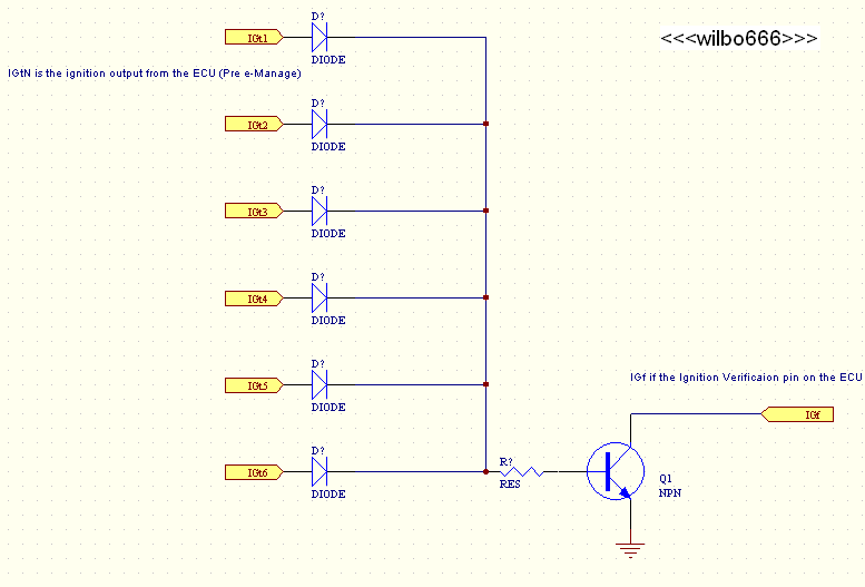
    Non-VVTi JZs are not wasted spark - they have 6 outputs and would need 6 igf pulses - try that first.
    If you're wasted sparking, are you sure you got the phasing correct?
    What JZ ECU are you running? Your setup sounds like a mess.

    Quote Originally Posted by Wizzard
    Maybe I am using too high resistors so not enough current going to IGf, does anyone know what current it expects? Or does anyone have a working circuit design? Seems to be nothing on the internet.
    The IGF that I have looked at are square waves, I'd expect the 2JZ to need a squarewave too. There is a time delay between the beginning of the trigger pulse and the igf pulse; if you set igf at the same time as igt it might not register as a valid igf signal. You shouldn't be concerned about the current - it's only voltage level based, not current. Have you looked at the waveform that your circuit provides?

    Take a look at this, page 4:
    http://lextreme.com/Adaptronic/1UZFE...ationNotes.PDF
    I havent tried it but in theory it works for 1UZ.

    Mos.
    Admin, I.T., Founding Member, Toymods Car Club Inc.
    2000 IS200 Sports Luxury 1UZ-FE VVTi, 1991 MX83 Grande 2JZ-GTE (sold)

  3. #3
    Is a Chief Engine Builder wilbo666's Avatar
    Join Date
    Sep 2005
    Location
    QLD
    Posts
    3,468

    Default Re: 1JZ faking IGf with a circuit

    As Mos says,

    2JZ-GTE non vvti is NOT wasted spark.

    You should have your emanage setup to run the spark in exactly this fashion. i.e. direct spark.

    I'm not familiar with the LS2 coils, is it single coil / igniter per unit and you have 6 of them? [edit, yes the LS2 coils are single coil and igniter]

    The stock 2JZ ecu expects an IGF signal for each spark event.

    The e-Manage Ultimate and the stock ECU could/can control the 6 spark signals.

    I did have a cro plot of the IGF ect signals from a JZ igniter, but can't seem to find it any more...

    You prbly read this thread and thought u needed 3?
    http://soarercentral.com/sc-forum/me...tml?1209208850

    Also Autoshp101 doc that might help...
    http://www.autoshop101.com/forms/h23.pdf

    Mos as a note the autoshop doc seems to show a different waveform to the Adaptronic waveform?

    There is also this...
    http://kerth.dyndns.org/supra/files/...Gf_circuit.pdf

    I suspect on the 2JZ you will need to diode the 6 ignition outputs to the IGf generating board so you get an IGf signal for each event

    Going off the 7mgte circuit that the PDF relates to, it would seem that grounding the IGf line when the ignition output line is high works...

    Maybe give the below circuit a go?


    Cheers
    Wilbo
    Last edited by wilbo666; 19-01-2013 at 07:27 AM.

  4. #4
    Founding ****** Automotive Encyclopaedia Mos's Avatar
    Join Date
    Jul 2005
    Location
    NSW
    Posts
    1,157

    Default Re: 1JZ faking IGf with a circuit

    Quote Originally Posted by wilbo666
    Mos as a note the autoshop doc seems to show a different waveform to the Adaptronic waveform?
    Yeah, and it's different to what I scoped (1G-FE) as well .. generational variation I say

    Quote Originally Posted by wilbo666
    Maybe give the below circuit a go?
    <snip>
    That won't do time delays, and won't do fixed pulse width, but I guess it depends how critical that is - the circuit is simple enough to try anyway.
    On the 1G-FE the igf was always the same time away from the trigger edge, and the same pulse width, regardless of rpm and regardless of the igt pulse width.

    I need to make one for the 1G at some point... now that Ed's nugget is finished I might actually have some time to try...

    Mos.
    Admin, I.T., Founding Member, Toymods Car Club Inc.
    2000 IS200 Sports Luxury 1UZ-FE VVTi, 1991 MX83 Grande 2JZ-GTE (sold)

  5. #5
    Junior Member 1st year Apprentice
    Join Date
    Jan 2006
    Location
    QLD
    Posts
    44

    Default Re: 1JZ faking IGf with a circuit

    Guys its a 2J in a Soarer (not a mess, as you would believe, all quite awesome). So I am using my 1J ecu, as rewiring my Soarer for a 2J ECU would be ..... The 1J ECU runs 2J's very very well, I can assure you (as you all know).

    Ok I thought the 1J was a waste spark, I have been given bum info, no problems will whip up that circuit Wilbo looks good to me electronics brain. Also I could just add another 3 trans. to my current circuit.

  6. #6
    Is a Chief Engine Builder wilbo666's Avatar
    Join Date
    Sep 2005
    Location
    QLD
    Posts
    3,468

    Default Re: 1JZ faking IGf with a circuit

    Quote Originally Posted by Mos
    Yeah, and it's different to what I scoped (1G-FE) as well .. generational variation I say


    That won't do time delays, and won't do fixed pulse width, but I guess it depends how critical that is - the circuit is simple enough to try anyway.
    On the 1G-FE the igf was always the same time away from the trigger edge, and the same pulse width, regardless of rpm and regardless of the igt pulse width.

    I need to make one for the 1G at some point... now that Ed's nugget is finished I might actually have some time to try...

    Mos.
    K,

    I don't recall what the CRO showed when I checked mine...


    You are 110% right that the circuit I showed is very simple, but I was just going off the fact that people have said it has worked in the past!


    Wizzard: Alarm bells should have been ringing in regards to wasted spark when you looked at the ECU pinout and saw IGt1 to IGT6

    Cheers
    Wilbo

  7. #7
    Junior Member 1st year Apprentice
    Join Date
    Jan 2006
    Location
    QLD
    Posts
    44

    Default Re: 1JZ faking IGf with a circuit

    Ah yes...hmm. Wilbo that soarercentral link is actually me ( I am Justin). No information for waste spark was in my brain from long ago. Also recently, read somewhere that some guy did one of these circuits with 3 transistors (hence why it sort of made my brain go...hmmm waste is right).

    Now I know! Never fiddled with ignition too much...first time, I will get it to work. If your circuit wilbo doesn't work, I will modify that one Mos send me from lextreme, with the diode inputs (from each) one, to give that RC circuit output onto the IGf.

  8. #8
    Junior Member 1st year Apprentice
    Join Date
    Jan 2006
    Location
    QLD
    Posts
    44

    Default Re: 1JZ faking IGf with a circuit

    Ah Wilbo, I know, but someone stated a long time ago, that even though there was 6 outputs it was wasted spark.

    I betcha the rumour started (we are talking 4 years ago now) because the injectors are batched fired....

    I haven't needed to research anymore since then...
    +1rep, although you guys don't need it.

  9. #9
    Founding ****** Automotive Encyclopaedia Mos's Avatar
    Join Date
    Jul 2005
    Location
    NSW
    Posts
    1,157

    Default Re: 1JZ faking IGf with a circuit

    Quote Originally Posted by Wizzard
    Guys its a 2J in a Soarer (not a mess, as you would believe, all quite awesome).
    Was talking mess engine management wise...

    Quote Originally Posted by Wizzard
    So I am using my 1J ecu, as rewiring my Soarer for a 2J ECU would be .....
    Rubbish .. rewiring any car properly is not a mess .. Running a car on the wrong ecu is just as much of a mess as a dodgy rewire....
    And I rest my case

    Quote Originally Posted by Wizzard
    The 1J ECU runs 2J's very very well, I can assure you (as you all know).
    As you have stated in your opening post that it doesn't run?
    I'm not trying to annoy you, but seriously, please don't try to convince anyone that running a 2JZ on a 1JZ computer is a "better" solution.... it's like running 20psi on a 2JZ with a FCD and a RRFPR... sure it works, but that's all that can be said...

    Quote Originally Posted by Wizzard
    no problems will whip up that circuit Wilbo looks good to me electronics brain. Also I could just add another 3 trans. to my current circuit.
    Easy enough to try all combinations.

    Quote Originally Posted by Wizzard
    Ah Wilbo, I know, but someone stated a long time ago, that even though there was 6 outputs it was wasted spark.
    It's amazing how misinformation spreads.

    Quote Originally Posted by Wizzard
    I betcha the rumour started (we are talking 4 years ago now) because the injectors are batched fired....
    Who started the rumous that the injectors are batch fired???? (THEY ARE NOT!!!)

    It's like those morons who think the Altezza 3S-GE is alloy block....

    Mos.
    Admin, I.T., Founding Member, Toymods Car Club Inc.
    2000 IS200 Sports Luxury 1UZ-FE VVTi, 1991 MX83 Grande 2JZ-GTE (sold)

  10. #10
    Is a Chief Engine Builder wilbo666's Avatar
    Join Date
    Sep 2005
    Location
    QLD
    Posts
    3,468

    Default Re: 1JZ faking IGf with a circuit

    Quote Originally Posted by Mos

    Who started the rumous that the injectors are batch fired???? (THEY ARE NOT!!!)


    Mos.
    1JZ-GTE is batch fired injectors...

    2JZ-GTE is sequential injection...

    I think he was referring to 1JZ

    Cheers
    Wilbo

  11. #11
    Junior Member 1st year Apprentice
    Join Date
    Jan 2006
    Location
    QLD
    Posts
    44

    Default Re: 1JZ faking IGf with a circuit

    Thanks Wilbo, thought I was going crazy for a second there. I make resistor packs for the Soarer and damn sure, Inj 1-4, 2-6, 3-5 are fired in pairs.

    My first 2J, so didn't know that they fired individually on their computer, good info to know.

    Plopping a 2J in a Soarer is very easy, but you put the 1J loom on the engine and I only had to modify one plug.

    Its not running because of this IGf crap. It was my choice to go aftermarket LS2 coils as it worked out $400 cheaper. Just required this extra research for this circuit. Should have kept the originals I know...you live and learn!

  12. #12
    Founding ****** Automotive Encyclopaedia Mos's Avatar
    Join Date
    Jul 2005
    Location
    NSW
    Posts
    1,157

    Default Re: 1JZ faking IGf with a circuit

    I thought I was going crazy
    Admin, I.T., Founding Member, Toymods Car Club Inc.
    2000 IS200 Sports Luxury 1UZ-FE VVTi, 1991 MX83 Grande 2JZ-GTE (sold)

  13. #13
    Junior Member Too Much Toyota oldcorollas's Avatar
    Join Date
    Aug 2005
    Location
    sydney
    Posts
    12,496

    Default Re: 1JZ faking IGf with a circuit

    resistors on injector power in pairs can still be fired individually tho...? they are coupled in the ECU, or ECU only has 3 inputs from injectors on 1J?
    "I'm a Teaspoon, not a mechanic"
    "There is hardly anything in the world that a man can not make a little worse and sell a little cheaper" - John Ruskin (1819 - 1900)

    AU$TRALIA... come and stay and PAY and PAY!!! The moral high horse of the world!

  14. #14
    Is a Chief Engine Builder wilbo666's Avatar
    Join Date
    Sep 2005
    Location
    QLD
    Posts
    3,468

    Default Re: 1JZ faking IGf with a circuit

    Quote Originally Posted by oldcorollas
    resistors on injector power in pairs can still be fired individually tho...? they are coupled in the ECU, or ECU only has 3 inputs from injectors on 1J?
    1JZ-GTE ECU only has 3 pins to drive injectors...

    If it can somehow still fire them sequentially with that I need a new brain?

    And stock 1jz-gte doesn't has high impedance injectors, so no resistors for them. For reference tho JZZ30 has two separate power feed wires in the loom for injectors tho

    Cheers
    Wilbo

  15. #15
    Founding ****** Automotive Encyclopaedia Mos's Avatar
    Join Date
    Jul 2005
    Location
    NSW
    Posts
    1,157

    Default Re: 1JZ faking IGf with a circuit

    VVTi 1JZs have sequential injection - 6 outputs - but not relevant here.
    The separate power feeds are only to reduce the current through the pins, they connect to the same conductor in a junction block.
    Admin, I.T., Founding Member, Toymods Car Club Inc.
    2000 IS200 Sports Luxury 1UZ-FE VVTi, 1991 MX83 Grande 2JZ-GTE (sold)

Similar Threads

  1. 1JZ vs 7M alternator useful info and pics
    By Ribfeast in forum Tech and Conversions
    Replies: 30
    Last Post: 22-06-2009, 05:10 PM
  2. Toyota diganostic error code, where can i find them?
    By MarkIIRx12 in forum Tech and Conversions
    Replies: 3
    Last Post: 19-03-2008, 01:42 PM
  3. 1jz vs 2jz heads
    By chris davey in forum Tech and Conversions
    Replies: 33
    Last Post: 04-05-2006, 10:07 AM

Bookmarks

Posting Permissions

  • You may not post new threads
  • You may not post replies
  • You may not post attachments
  • You may not edit your posts
  •