Page 3 of 3 FirstFirst 123
Results 31 to 45 of 45

Thread: Need help with SP1 wire into ECU (1JZ Cressida)

  1. #31
    Least it doesnt snore Backyard Mechanic Gary's Avatar
    Join Date
    Dec 2007
    Location
    Victoria
    Posts
    308

    Default Re: Need help with SP1 wire into ECU (1JZ Cressida)

    would you be so kind?
    JZX83
    UCF11

  2. #32
    Least it doesnt snore Backyard Mechanic Gary's Avatar
    Join Date
    Dec 2007
    Location
    Victoria
    Posts
    308

    Default Re: Need help with SP1 wire into ECU (1JZ Cressida)

    apparently not

    in case anyone has a simlar drama to me;

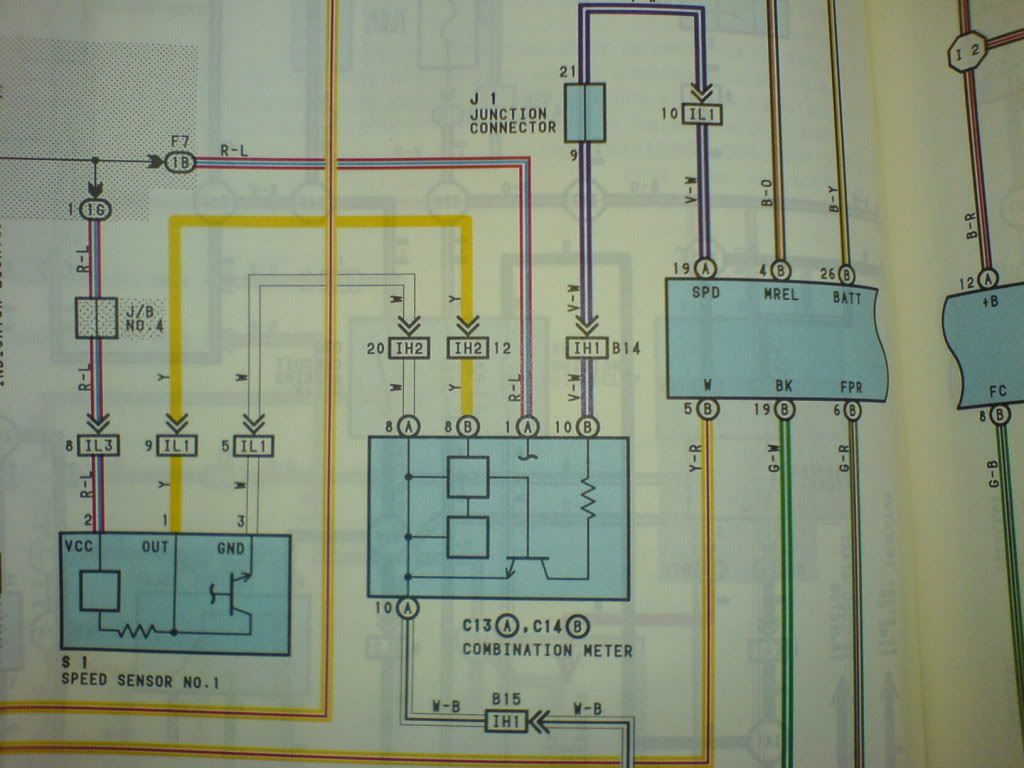
    as far as i can see for the S1 cluster, SP1 comes from the blue/red pin on the grey 10pin plug, and the speed input comes in via cable (mechanical)

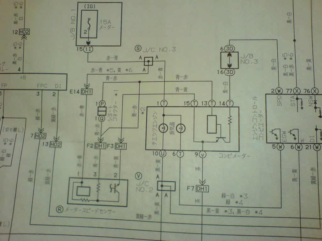
    the S2 cluster seems to get its speed input via the same pin as the S1 cluster outputs it to the ecm. so i think, the speed sensor goes into the blue/red pin on the grey 10pin plug. SP1 comes from the lightgreen/red wire a couple pins across, maybe
    on the S1 loom its blue/red, on the S2 loom the same pin is yellow/green

    cars not running at the moment so i havent checked if it works, but thats it as far as i know. ill update the shit later
    JZX83
    UCF11

  3. #33
    Toymods V8 Member Too Much Toyota CrUZida's Avatar
    Join Date
    Aug 2005
    Location
    WA
    Posts
    8,214

    Default Re: Need help with SP1 wire into ECU (1JZ Cressida)

    The GX81 diagram I have is for a speed cable, not electronic sender.
    Peewee
    1985 MZ12 Soarer - 1UZ Powered
    2013 86 GTS

  4. #34
    Founding ****** Automotive Encyclopaedia Mos's Avatar
    Join Date
    Jul 2005
    Location
    NSW
    Posts
    1,157

    Default Re: Need help with SP1 wire into ECU (1JZ Cressida)

    The electronic speedo will have 4 screw terminals on it. Two are power and ground, one is signal in, one is signal out. If you know which one is SP1, you can work out which one is signal in... The label for SP1 is 4P, and signal in is some Japanese character.
    Yes I do have the pinouts (somewhere - worked out myself) but it's easy enough to work out off the cluster itself - I had to retrofit a S1 dash loom into a S2 cressida.

    The speed signal is the yellow wire in the plug that carries the water temp and oil pressure signals (and gear selection lights) and goes directly from the engine loom to the dash loom (it's the pin the S1 does not have). The dash loom plugs directly into the cluster. The engine loom connects to the gearbox loom which connects to the speed sensor - powered from the (IIRC) gauge fuse through the larger grey connector, and grounded to the engine. If you hook the speed sensor output directly into the cluster it should work.

    Mos.
    Admin, I.T., Founding Member, Toymods Car Club Inc.
    2000 IS200 Sports Luxury 1UZ-FE VVTi, 1991 MX83 Grande 2JZ-GTE (sold)

  5. #35
    Least it doesnt snore Backyard Mechanic Gary's Avatar
    Join Date
    Dec 2007
    Location
    Victoria
    Posts
    308

    Default Re: Need help with SP1 wire into ECU (1JZ Cressida)

    Quote Originally Posted by CrUZida
    The GX81 diagram I have is for a speed cable, not electronic sender.
    all good man, cheers anywho

    mos that first paragraph is interesting, more or less confirms SP1 'output', the other terminal with the jap characters ends in a dead end though - which for me and my obviously stellar understanding of electrical track board floppy plastic blue stuff, didnt help me seems logical now that the soldered terminal opposite to the dead end leads to the same pin ive nutted out via ripping into an S2 cressidas loom. so that sorta confirms what i was on in my post above

    cheers pretty confident it'll work now. might knock a diagram up or something if anyone else has had the same annoying time ive had working this shit out
    JZX83
    UCF11

  6. #36
    Founding ****** Automotive Encyclopaedia Mos's Avatar
    Join Date
    Jul 2005
    Location
    NSW
    Posts
    1,157

    Default Re: Need help with SP1 wire into ECU (1JZ Cressida)

    Use a multimeter
    Off the photos you posted, the jap char looks like it travels up to the plug directly above it (pin 6 from the right), through one jumper (piece of wire soldered on both ends - if you lift the pcb slightly you should see a short piece of wire soldered to the two pads "jumping" the other trace). 4P ends up on pin 4.
    It seems the jap char also goes to pin2 of the left most connector in the photo, though I can't remember what that could've been for.
    Mos.
    Admin, I.T., Founding Member, Toymods Car Club Inc.
    2000 IS200 Sports Luxury 1UZ-FE VVTi, 1991 MX83 Grande 2JZ-GTE (sold)

  7. #37
    Least it doesnt snore Backyard Mechanic Gary's Avatar
    Join Date
    Dec 2007
    Location
    Victoria
    Posts
    308

    Default Re: Need help with SP1 wire into ECU (1JZ Cressida)

    dunno what that other pin does, i traced it down to an orange plug behind the drivers kick panel, which im pretty sure heads up and away behind the dash and back where the ECM is... i'll see if i can find out its the same wire as the speed input to the S2 cluster so could be important
    JZX83
    UCF11

  8. #38
    Founding ****** Automotive Encyclopaedia Mos's Avatar
    Join Date
    Jul 2005
    Location
    NSW
    Posts
    1,157

    Default Re: Need help with SP1 wire into ECU (1JZ Cressida)

    If the orange plug has 5 wires on it it could be the progressive power steering ecu, though I would've thought it would've come off the SP1 signal.. hmm..
    Admin, I.T., Founding Member, Toymods Car Club Inc.
    2000 IS200 Sports Luxury 1UZ-FE VVTi, 1991 MX83 Grande 2JZ-GTE (sold)

  9. #39
    Toymods V8 Member Too Much Toyota CrUZida's Avatar
    Join Date
    Aug 2005
    Location
    WA
    Posts
    8,214

    Default Re: Need help with SP1 wire into ECU (1JZ Cressida)

    Quote Originally Posted by Mos
    though I would've thought it would've come off the SP1 signal.. hmm..
    So would have I. Infact, I would have comfortably bet money on it.

    Cruise control runs off SP1
    Peewee
    1985 MZ12 Soarer - 1UZ Powered
    2013 86 GTS

  10. #40
    Least it doesnt snore Backyard Mechanic Gary's Avatar
    Join Date
    Dec 2007
    Location
    Victoria
    Posts
    308

    Default Re: Need help with SP1 wire into ECU (1JZ Cressida)

    the orange plug has 9pins in use out of 11 or something

    that other pin (one that seems to share the SP1 track on the cluster) could possibly be for cruise etc, it leads down to a corner i cant quite get to without removing lots more things

    i might have em round the wrong way, lightgreen red should be speed input and the two yellow and green pins might be SP1 (yellow/green and blue/red for S2)
    Last edited by Gary; 02-12-2008 at 09:08 PM.
    JZX83
    UCF11

  11. #41
    RZN169R+2JZGTEVVTI+R151 Domestic Engineer madmont's Avatar
    Join Date
    Nov 2005
    Location
    Queensland
    Posts
    669

    Default Re: Need help with SP1 wire into ECU (1JZ Cressida)

    Here is the circuit you need to reproduce to make the electronic speedo work

    and in english

    These are factory diagrams and the numbering on the speed sensors is different although I would expect them to be the same
    Last edited by madmont; 03-12-2008 at 10:51 AM.
    Jealousy is a curse

  12. #42
    Junior Member Backyard Mechanic benjamin's Avatar
    Join Date
    Sep 2005
    Location
    NSW
    Posts
    237

    Default Re: Need help with SP1 wire into ECU (1JZ Cressida)

    Alright, Im bumping an old thread but I am having difficulty with getting my speedo to work. I have a series 1 cressida, but I have taken the electric speedo sender and dash cluster from a series 2. I have connected the yellow wire off the sender, directly to the terminal with the japanese characters on the back of the cluster(ie next to the one that says 4P). The black wire to earth and the red wire to 12v+(ign). I don't get any movement on the needle and I am hoping someone can shed some light on this for me. Does the red wire connect to 12v+ or is this incorrect?
    Last edited by benjamin; 23-06-2012 at 08:31 AM.

  13. #43
    Junior Member Backyard Mechanic benjamin's Avatar
    Join Date
    Sep 2005
    Location
    NSW
    Posts
    237

    Default Re: Need help with SP1 wire into ECU (1JZ Cressida)

    ok i have now checked the sender by spinning it in a drill and testing that the yellow wire is earthing. That seems like it works as my multimeter pulses when its being turned. Do I need to feed additional power inputs to the series 2 cluster if the standard cluster wiring is for a mechanically driven speedo?

  14. #44
    Junior Member Backyard Mechanic benjamin's Avatar
    Join Date
    Sep 2005
    Location
    NSW
    Posts
    237

    Default Re: Need help with SP1 wire into ECU (1JZ Cressida)

    Success! The negative pickup on the back of the (series 2) speedo needs to be earthed as the standard loom (series 1) doesn't seem to have the provision for this. On the back of the cluster there is a black wire going from the tacho earth over to a point behind the temp gauge and then up to pin 3? on the 11 pin plug and this isn't an earth on the series 1. So after hardwiring a new earth my speedo needle moves. Now I just have to get it calibrated...

  15. #45
    Forum Member
    Join Date
    Sep 2015
    Location
    nsw
    Posts
    2

    Default Re: Need help with SP1 wire into ECU (1JZ Cressida)

    where are you finding this series 2 diagrams

Similar Threads

  1. ECU pinouts Gen 3 1GGZE (Definitive?)
    By infotechplus in forum Engine & Driveline Conversions
    Replies: 29
    Last Post: 24-09-2017, 11:29 PM
  2. 1jz or 2jz for cressida
    By FreeStyler in forum Tech and Conversions
    Replies: 20
    Last Post: 01-08-2013, 07:45 PM
  3. 1JZ ECU leaking capacitors.
    By Slim in forum Tech and Conversions
    Replies: 25
    Last Post: 03-03-2010, 09:29 PM
  4. 1JZ into MX83 Cressida Conversion
    By matt100kw in forum Tech and Conversions
    Replies: 2
    Last Post: 18-03-2007, 10:06 AM
  5. Cressida MX73 Conversions Guide Book
    By twentyEight in forum Engine & Driveline Conversions
    Replies: 12
    Last Post: 24-02-2007, 11:07 AM

Bookmarks

Posting Permissions

  • You may not post new threads
  • You may not post replies
  • You may not post attachments
  • You may not edit your posts
  •