


i thought id help out a bit as im wiring in my ecu, ive looked around and came up with nothing to do with the engine wiring diagrams, and im not a fan of payin 183 dollars for the toyota book unless i need to. so here it goes it isnt finished yet but may help someone out in the future. as i finish wiring ill complete the rest.
Ignition wire :
Stock ecu (run it over to the ignition barrell the one in the stock loom cant support the power draw from the relays)
Throttle position sensor :
Stock ecu Yellow : (signal out)
Stock ecu Green/yellow trace : (5v input from ecu)
Stock ecu Light green/black trace : (Ground)
Cam angle sensor :
(dont need it if you set the injectors up to run batched)
Stock ecu Black : (ground) (the cam angle sensor is not needed)
Stock ecu White : (signal out)
Crank angle sensor :
(
the loom wire colors change from the plug going to the sensor and the plug going to the ecu, those combinations are from sensor to plug)
stock ecu Red (shielding)
Stock ecu Green (trigger)
Stock ecu Brown/White dots (ground)
Injector 1 :
Stock ecu Black/pink trace (12v)
Stock ecu Red/blue trace (ground)
Injector 2 :
Stock ecu Black/pink trace (12v)
Stock ecu Blue (ground)
Injector 3 :
Stock ecu Black/pink trace (12v)
Stock ecu White (ground)
Injector 4 :
Stock ecu black/pink trace (12v)
Stock ecu Red (ground)
to just use 2 injector banks ive linked injector 1 and 3, and 2 and 4 together
(note : opposite to how the wasted spark ignition works)
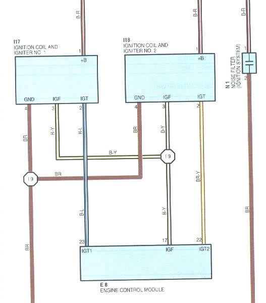
Coil packs :
stock ecu black/red trace (12v)
stock ecu blue/white trace (ignition trigger)
stock ecu brown (ground)
stock ecu white/black trace (misfire recognition/tacho) not used on aftermarket ecu's
thanks to richard for that diagram
as the diagram said ignition 1 output from the ecu goes to coil pack 1,4 . ignition ouput 2 goes to coil 1,3
the 3rz coils have built in ignitors hence the 3 wires instead of the 2.
Idle Motor
stock ecu
stock ecu havnt go that far yet.
stock ecu
stock ecu
NOTES : for people that dont know everything
- The crank angle sensor is magnetic NOT hall effect
- Cam angle sensor is used as HOME but not needed.
- The cas is a 34 tooth wheel, but in the trigger setup it needs to be put in as 68 tooth
(i have trigger btdc set to 53 degrees and offset set to 4)
Last edited by BeRad; 29-04-2007 at 03:25 PM.
Only the shittiest of wines come in 5 litres
boosted 3rz hilux *new project* mwahaha
http://www.toymods.net/forums/showth...940#post134940
 Posting Permissions


 Reply With Quote
Bookmarks