


 Reply With Quote
i knew there might have been a mistake somewhere because normally things don't work out this hard haha, thanks for all your help Mos +rep for you


That would explain some of it.Originally Posted by chaserbuddy
That should fine, provided that part of the water pump gets hot enough, fast enough. Electrically that should be fine but I would use the crimp spade connectors on these as well.
Only proviso, and I'm sure you know it, is to use black for ground, but obviously it won't stop it from working.
Unfortunately what you have hooked up is not correct. I just realised Witzl screwed up the diagramI owe you an apology - sorry
The first relay works.
The second relay has both the batt and fan connected to either two pin 87 or one 87 and one 87a depending on what kind of relay you have used. What you should have hooked up is the batt to pin 30 and the fan to pin 87a (87a is correct as long as it's an 87/87a relay).
Being pedantic, and once again won't stop it from working, is that "ign" should be a red wire by convention.
87 and 87a are never connected together, and I have never seen 86/86a in that fashion.
Below are the standard relays commonly available - all have pins 85 and 86 as the solenoid, and applying power across those pins activates the relay.
The first is a 4 pin, normally open type, with an input on pin 30 and a single ouput on pin 87.
The second is a 5 pin, normally open type, with an input on pin 30 and two outputs on two pins marked 87.
The third is a switching or "change over" 5 pin, with an input on pin 30, a normally closed output on pin 87a and a normally open output on pin 87. Sometimes the "a" is printed away from the 87 and is not immediately obvious.
Witzl's setup is correct provided the correct relays are used.
Should be something like this:
This circuit operates as follows:
An NO setup will be fine, and is simpler than an NC setup.
This circuit operates as follows:
In your case, replacing the "ground" wire on the first relay with the wire from the thermostat should work.
HTH.
Mos.
Last edited by Mos; 30-10-2008 at 04:00 AM. Reason: Added diagram
Admin, I.T., Founding Member, Toymods Car Club Inc.
2000 IS200 Sports Luxury 1UZ-FE VVTi, 1991 MX83 Grande 2JZ-GTE (sold)
i knew there might have been a mistake somewhere because normally things don't work out this hard haha, thanks for all your help Mos +rep for you
Last edited by chaserbuddy; 30-10-2008 at 12:43 PM.
If your running two fans, does one power cable to to the first fan and then bridge to the next fan aswel? Or do you need more relays?
And mos, on the first relay in the two relay configuration, how come battery power goes to the wire that goes to the second relay? Wouldnt that mean that even when ing is off, the 2nd relay will stay powered? Or am i just wrong
Cheers,
Jase
yes bridges to the other fan. i think i can help with the second question aswell when to coil is uncharged i.e ignition off, the switch switches back, stopping the battery power from going though the switch and to the next relay.
Personally I would not bridge a second fan off the same relays. Even though the relays are rated at 20 or 30 Amps, the spade pins are only rated around 15A, and a single relay and base will melt over time with two fans (had it happen). For peace of mind, a single fan per circuit
And yes, when you turn the ignition off, the relay solenoid is de-energised and the relay contact opens.
Admin, I.T., Founding Member, Toymods Car Club Inc.
2000 IS200 Sports Luxury 1UZ-FE VVTi, 1991 MX83 Grande 2JZ-GTE (sold)
Nice write up Mos!
I was almost about to draw up the cct myself, but was lazey ;p
-A
Four Cam Inside The VG30DET+T powered MA61.. actually running, really it is!, no wait its broken again...
The Lithium Ion Powered Sera EV Conversion, Getting some upgrade love.
Latest member: The AW11 MR2 'Trouble'
280ZX Now with RD28 Turbo conversion. Actaully finished!
The good thing about the whitzls diagram aswell as toyota factory, when you remove the plug from the thermo switch on the remote thermo housing (4age ae82) the thermo turns on.
KE30 4agte - Bullet - Rick Rolled
UZX83 1UZ W58- Cruiser - Tow Car - Fun Car


What switch range is everyone using for the 1JZ, I have a 95 on 90 off, the engine at idle runs at 96-98 so the fans never switch off, maybe i have the wrong range, maybe there is an issue with the rad .....what do you think?
You either need a higher rated switch or a lower rated thermostat.
I'd be more inclined to get a cooler thermostat.
Daily Driver: Red Ae93 Project: My TA22 - now with 3s-gteD is for Disco, E is for Dancing
So in total i'll need 4 relays?? 2 for each fan??
Cheers,
Jase
Hey - i made a booboo... and it took 3 years for people to work it out!!
LOL t o y m o d s !
...... butt scratcher?!
If you want to wire it up like this and be sure it won't melt, yes
You could chance it - I did, once, and never will again (with two fans drawing under 7A each (measured) with 30A relays). I do, however, tend to hook them up with NO thermostats to reduce the number of relays.
Toyota uses 30A circuits and 8.5mm connectors for fans and they would have done sufficient R&D to determine that this was the most optimal solution.
So is that saying that no one has used the informationIt "looked" right, I just never had a good look for the pin number on the relays
Mos.
Admin, I.T., Founding Member, Toymods Car Club Inc.
2000 IS200 Sports Luxury 1UZ-FE VVTi, 1991 MX83 Grande 2JZ-GTE (sold)
can someone explain the failz to me. ive used the diagram straight up and it works fine.
KE30 4agte - Bullet - Rick Rolled
UZX83 1UZ W58- Cruiser - Tow Car - Fun Car
It required the relay to make a connection between 87 and 87A which means it will do nothing. If you substitute a relay with two 87pins, then it just shorts and runs the fan full time.
Admin, I.T., Founding Member, Toymods Car Club Inc.
2000 IS200 Sports Luxury 1UZ-FE VVTi, 1991 MX83 Grande 2JZ-GTE (sold)
ok so im wiring my microtech to twin thermos in a 23 celica. just posting here so folks can see how im doing it with the single output from the comp
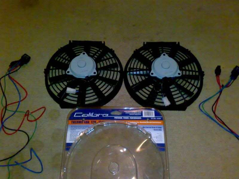
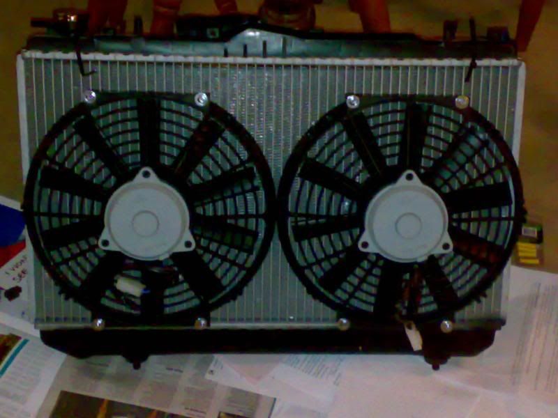
i bought 2 supercheap 12" thermos. the brand is calibre and they go for about $60 each.
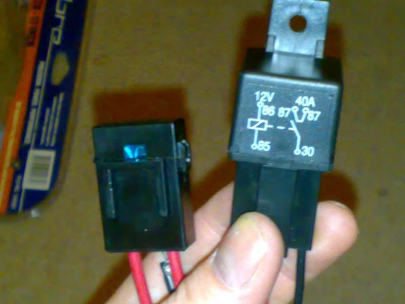
the relays that are supplied are 40A so im happy to just run the signal from the microtech in parrallel to each relay for switching (for the n00bs this means the power remains the same for the signal wrather than being split in two when you wire in series, which will halve the 6v power (which is what i think microtech runs at) output to 3v which is hardly sufficient (i think)) the other black box jigga that you can is a 15A fuse, which is also supplied
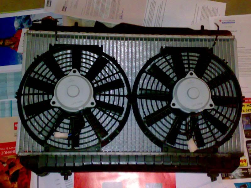
the fans are to be mounted on a hyundai excel radiator which looks like this
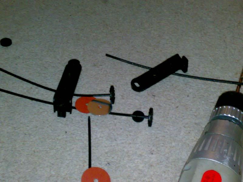
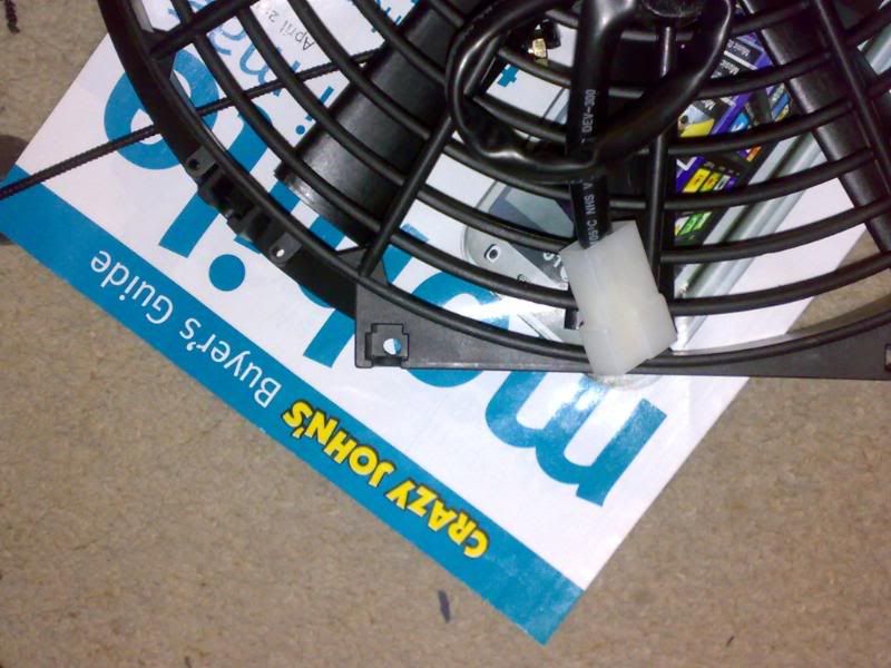
so mounting the fans is the biggest pain in the arse you're gunna have to deal with. first off you get given a whole bunch of shit, nfi how your supposed to use it. and ofcourse the fins will never line up the way you would like them to
or you could just line it up and drill through the fan housing itself. much easier.
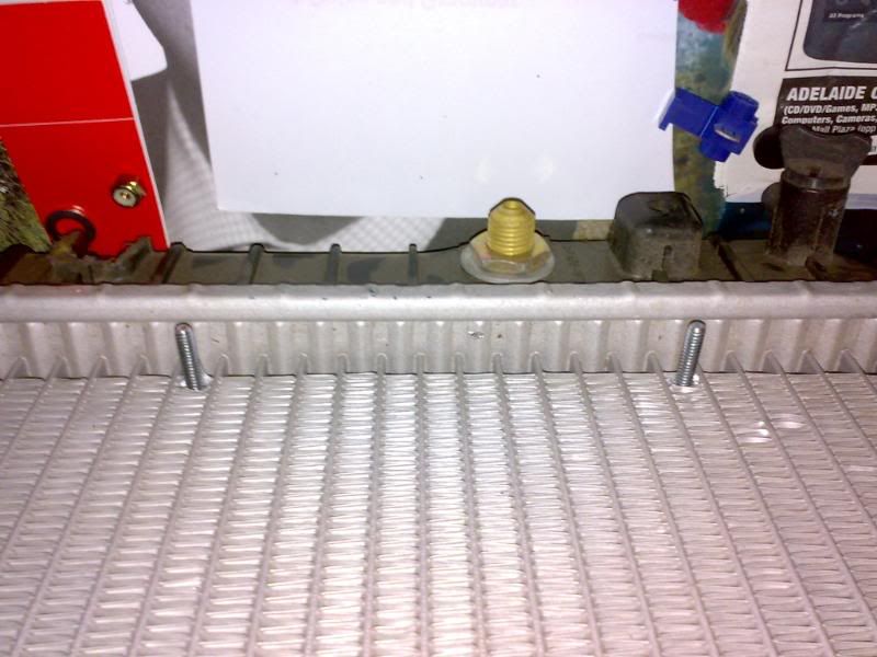
then put you bolts in and gently tap them. this will show you where to pry apart the radiator fins for you bolts. i drilled mine. i found it doesn't acutally remove any material, it separates in nicely though
finished
EDIT: this will be edited as i go
Last edited by SillyCarS; 15-04-2009 at 09:03 PM.
 Posting Permissions


Bookmarks