
 Reply With Quote
I am considering it....


MWP any plans to sell your can bus controller?
1990 ST185 Running stock Gen 3 power, 216awhp at 15psi. 13.6 second down the quarter


I am considering it....
Daily: Toyota '05 Rav4 Sport
Projects: Celica GT4 ST185 (5S-GTE), Celica RA28 Celica (1UZ-FE)
Previous: Corona RT104, Starlet GT Turbo
Classic Celica Club of South Australia
We have an ACA33R Rav4.... i have to say im not a huge fan of the electric power steering, it just doesnt feel "right". Especially when i jump from the Rav to the Caldina, or the other way around.
...... butt scratcher?!
Drive a '86 or LFA... see if you think the same thing about their electric power steering
I need to get my hands on a Toyota scan tool thingie.
The service menus in it can adjust a few more EPS params.
Last edited by MWP; 19-02-2014 at 01:07 AM.
Daily: Toyota '05 Rav4 Sport
Projects: Celica GT4 ST185 (5S-GTE), Celica RA28 Celica (1UZ-FE)
Previous: Corona RT104, Starlet GT Turbo
Classic Celica Club of South Australia
I got it fitted up today.
Everything is just tack welded in place for the moment.
Not much room to spare fitting the EPS motor in.
I powered it up, and it works great... with the car standing still anyway

Last edited by MWP; 19-02-2014 at 03:50 AM.
Daily: Toyota '05 Rav4 Sport
Projects: Celica GT4 ST185 (5S-GTE), Celica RA28 Celica (1UZ-FE)
Previous: Corona RT104, Starlet GT Turbo
Classic Celica Club of South Australia
Good work Mark. It'll need to be in more advanced kit form to sell id think? But an option id look at for sure.
Lily Simpson 6.7.2010
R.I.P.
Smee (PF) is interested for his rally 'rolla, so ill have to package it up into something half decent looking & bullet proof for him.
I'll get that done, and go from there...
Daily: Toyota '05 Rav4 Sport
Projects: Celica GT4 ST185 (5S-GTE), Celica RA28 Celica (1UZ-FE)
Previous: Corona RT104, Starlet GT Turbo
Classic Celica Club of South Australia
First of MWP i am glade to see someone else taking on this custom setup!
Now i have been working on getting some way to duplicate the can network to get my setup to function at full capacity. While doing much research into this and greatly expand on my understanding on the can bus system. So to start i would like to explain a little about the can system. Robert bosch developed the can system back in the 80. By about 2004 most manufacturers adopt the can system. If you are looking into this mod i would suggest you do some research into and understand the can system.
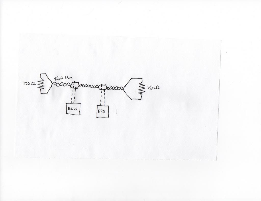
The basic of the system setup is two communication wire twist together. Each end of both wires are terminated with a 120 ohm resistor. Then each of the ecu are wire has branch of the main.
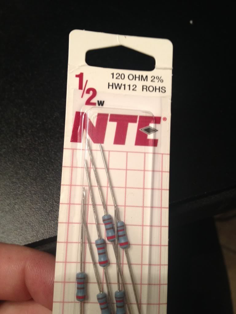
Sorry for my bad drawing. The 120 ohm resistor can be located on toyota vehicles in many location. Like a junction connector or even inside an ecu. The good thing is the yaris that my eps ecu is from, toyota put the resistor inside the eps ecu. So to wire mine up i only need a single 120 ohm resistor.
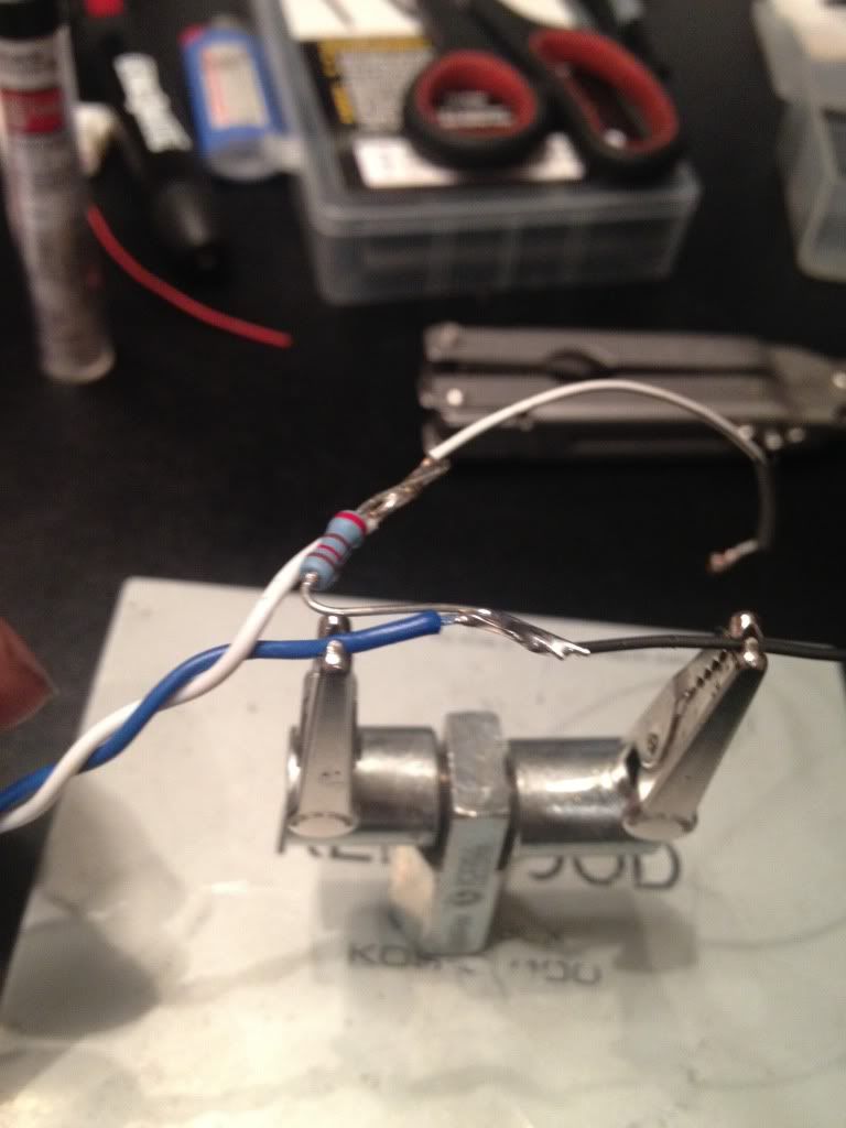
Make sure your resistor is after your wiring connection.
Then i heatshrinked over the resister and taped. There should not be much heat since its low voltage a wattage.
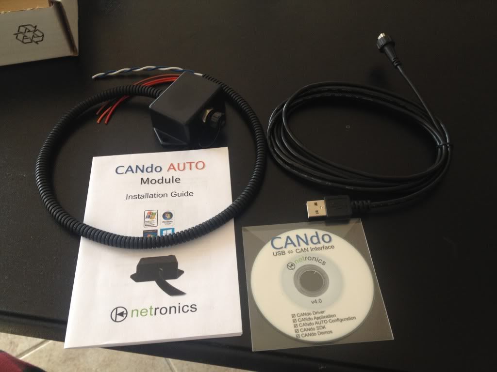
I did much research into how to duplicate the can network. My first direction was a arduino uno board with a can shield tranciever. The arduino uno i had and while researching which can shield to use i came acrossed a device from a company in england http://www.cananalyser.co.uk/candoauto.html
The cando auto unit spec looked to meet my needs and have software to boot. Which ment less time programing the ardunio.
So i order one. Getting it wired up and then started the fun part, programing it!
I found some great sites for information and one guy who actually had a youtube video of raw recorded can data from a yaris. http://fabiobaltieri.com/2013/07/23/...and-socketcan/
I going to jump in to technical which will make much more since once you research the can system. I was able to find the hex decimal code for engine rpm is 2C4 wheel speed is either 0B0 or 0B2. Since my setup non abs eps ecu has an analog wheel speed signal. I only needed the engine rpm on the can network so i will only go over how i programed the cando for this. The cando has 2 analog input that can be programed to then transmit a programable can data. It also can have ten static data points programed and continually repeted. When you get the software open there are four tabs. "Input view", "inut setup", "can transmit" and "can setup" first off we need to go to "can setup" and change the setting to 500kps to match the network speed of the can system. Then back to the tab "can transmit". Now has i said earlier the hex for rpm is 2C4. The data length is 11 bit. The dlc is 8. The information i used was ramdomly picked after much trial and error. Almost 3 pages of codes I tried. I could set a rpm in connect my scan tool and see the rpm but still now assist. After much frustration i finally realised that it was a setting i had wrong. It was how often i had it repetting the message. The end result looked something like this 2C4 8 06 8A 00 19 00 00 92 09 Repet rate 20 ms(milliseconds) . All this done and turned the car on and immediate assist. I still have not been able to drive the car and see if it feels bettter. Still working on some idle issues with the engine. I could however tell the assist was greater. Last thing to work on is connecting the can wiring to the dlc so i can see about changing the setting for the assist level at idle.
So more site with good information on can and it relation to toyota vehicles.
http://tucrrc.utulsa.edu/ToyotaCAN.html
https://www.scantool.net/forum/index.php?topic=5895.0
http://www.countermeasure2013.com/do...trol_Units.pdf
http://illmatics.com/car_hacking.pdf
http://fabiobaltieri.com/2013/07/23/...and-socketcan/
Hope this all help. Feel free to ask any questions. I will help where i can.
Last edited by Ae95/4agze; 23-02-2014 at 02:18 AM.
Check out my ae95 4agze sc14 build. http://www.alltracwagon.net/forum/m-1347147405/ or check out the ride info at http://www.toymods.org.au/forums/for...agze-sc14.html
Have driven 86, not for very long tho, and found it was good.Originally Posted by MWP

Unfortunately i dont have enough coins to drive an LFA.
...... butt scratcher?!
The Toyota's ive looked at put one 120ohm resistor in the ECU, and the other in the dash (combination meter).
So there is no need to put another on whatever it is your plugging into the ODB2 connector. Using another can actually stop the whole canbus from working.
Because the OBD2 port is a "spar" (side line off the main ECU->dash canbus), wire length needs to be kept short, no longer than about 30cm.
Daily: Toyota '05 Rav4 Sport
Projects: Celica GT4 ST185 (5S-GTE), Celica RA28 Celica (1UZ-FE)
Previous: Corona RT104, Starlet GT Turbo
Classic Celica Club of South Australia
Toyota has put the 120 ohm termianting resistor in several location, it all depends on the car. I have seen them in ecu, cluster and even inside a junction connector. The 2007 yaris eps ecu i used just happen to have the 120 ohm resistor. That resistor makes up one end of the can network. But the system needs both end terminated. And since i am not using the component that has the second resistor is why i wired in the second resistor. To complete the network. Then i wired the cando auto module in between the resistor and the eps ecu. With that done the system is now working. I can connect mr factory toyota master tech scan tool to the eps ecu and see the love data showing my fake rpm signal. The code for the failed can communication with engine ecm is gone.
You are correct that you need to keep the spar of the main can line has short has possible.
Check out my ae95 4agze sc14 build. http://www.alltracwagon.net/forum/m-1347147405/ or check out the ride info at http://www.toymods.org.au/forums/for...agze-sc14.html
EPS column install is now finished
Now its just a matter of putting the EPS controller box somewhere, and running the power wires.
Modified shaft/uni's.
EPS column mounts all fabbed & welded up.
EPS motor mounted.
Final testing.

Daily: Toyota '05 Rav4 Sport
Projects: Celica GT4 ST185 (5S-GTE), Celica RA28 Celica (1UZ-FE)
Previous: Corona RT104, Starlet GT Turbo
Classic Celica Club of South Australia
 Posting Permissions


Bookmarks