Results 1 to 13 of 13

Thread: 5SFE wiring issues with later model engine

  1. #1
    Junior Member Backyard Mechanic DrNick's Avatar
    Join Date
    May 2008
    Location
    WA
    Posts
    206

    Default 5SFE wiring issues with later model engine

    I've been staring at this for hours now and can't suss it out.

    The vehicle is a 1990 ST184 Celica. I have just swapped in an engine from a 1993 ST184. This would be a series 2 engine so I was expecting there to be some differences.

    I have also got the loom and ECU from the 1993 vehicle so it should have been plain sailing. However I have discovered that there are plugs which don't match up now. I've tried matching colours and had limited success as some of them have completely different colours.

    I figured the engine is so common that someone will be able to advise me here.

    Problem 1. Smashed plug on alternator. Don't know which way the wires go around.

    Here is my best guess but it really is just a guess.


    Problem 2. No plug fits into the ignition coil. There are two candidates which are nearby in the loom but neither of them fit. What is more worrying is that those two plugs do not share wires with the igniter at all which makes me doubt whether they are the right ones at all (On series 1 there are 2 wires in the coil, Black/Orange and White/Blue and both of these are connected to the igniter)

    The coil


    The plug on the old engine


    The two nearby plugs in the new loom which don't fit or share wires


    Problem 3. Reverse light

    (At least I think thats what it is) Here is the plug on the gearbox


    On old engine this goes in with two wires


    Nothing matches on the new loom but this one is nearby. Again , different coloured wires and different plug


    Any help will be much appreciated. I've spent ages putting this thing together and I just have these silly wiring issues left.

  2. #2
    Junior Member Grease Monkey progkamol's Avatar
    Join Date
    Feb 2006
    Location
    WA
    Posts
    152

    Default Re: 5SFE wiring issues with later model engine

    Someone correct me if I'm wrong ... but I think there should be 2 wiring loom come out from the fire wall, the driver's side and the passenger's side. I have had problems before in an RX7 FC (Series 5 motor into a Series 4) where wires doesn't match up. Starting with the wires to the coil packs, it was easily solved on the RX7 by replacing the passenger's side wiring loom which goes direct to the ECU. If you havn't done this already, you might wanna consider pulling the whole loom out ratehr than cut & joints. So the easiest way by sound to solve this problem is to change the whole wiring loom (if you can get them). By saying the easiest way by sound means that its sound easy but its bloody hard to do lol ... Don't know if I'm much help or not but good luck with it ... hope you, or someone here help you, sort it out soon
    Signed
    M4C

  3. #3
    you can't say ****** here Automotive Encyclopaedia CLG's Avatar
    Join Date
    Aug 2005
    Location
    Perth WA
    Posts
    954

    Default Re: 5SFE wiring issues with later model engine

    Nick, I've got an ST204 sitting in the driveway, will go through and try to answer your questions tomorrow, give me a call tomorrow evening.

  4. #4
    Junior Member Backyard Mechanic DrNick's Avatar
    Join Date
    May 2008
    Location
    WA
    Posts
    206

    Default Re: 5SFE wiring issues with later model engine

    I just had a quick look at the car before I left for the office this morning, and I think the distributor may be one with an internal coil. So that would explain why I cant find anything to plug into the coil Although that means theres a whole handful of plugs in the new loom that have nowhere to go!
    I'd be pleased if its internal as its one less thing to worry about.

    The next biggest thing is the plug on the alternator and what order those 3 wires go into the connector.

  5. #5
    Is a Chief Engine Builder wilbo666's Avatar
    Join Date
    Sep 2005
    Location
    QLD
    Posts
    3,468

    Default Re: 5SFE wiring issues with later model engine

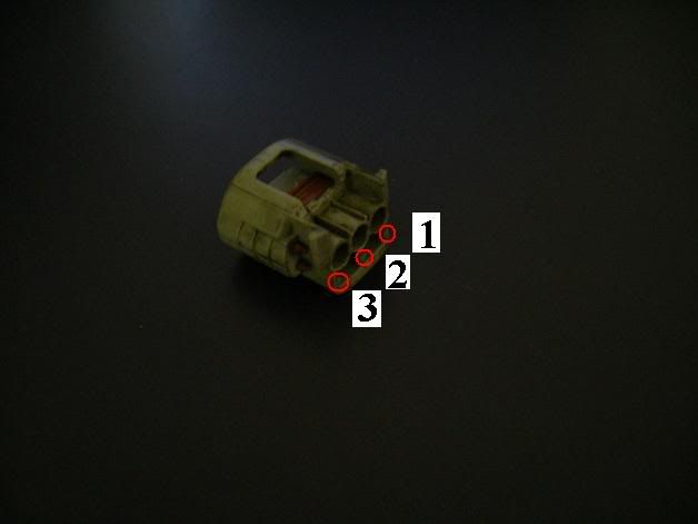
    Pin 1 = L = Charge Light, Black / Orange Wire
    Pin 2 = IG = Ignition, Yellow Wire
    Pin 3 = S = Sense Wire, White Wire

    Pin numbers are on the back of the plug (cast into the plastic). Currently you need to swap 1 with 3 from what I can see...

    Wire colours come off a JZA80 wiring diagram, but expect them to be the same, I'd be very surprised if they were different, but you have been told


    Cheers
    Wilbo
    Wilbo's Wiki (Includes 2JZ-GTE Wiring, etc! )

    Wilbo's JZA80
    Wilbo's JZZ12

  6. #6
    Junior Member Backyard Mechanic DrNick's Avatar
    Join Date
    May 2008
    Location
    WA
    Posts
    206

    Default Re: 5SFE wiring issues with later model engine

    The wire colours sound familiar so I would reckon they are right.

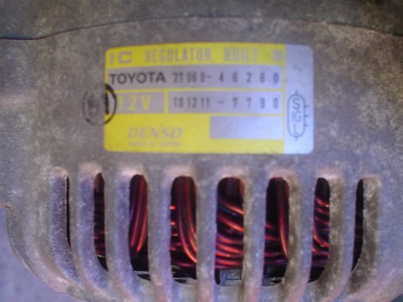
    I have this diagram on the alternator but unsure if it is of the connector or of the socket in the alternator itself


    This is the bit of the connector that I have - no pin numbers moulded into it


    So my guess was that the diagram is looking down onto the connector like this


    Which gives

    White (S)
    Yellow (IG)
    Black/Orange (L)

  7. #7
    Is a Chief Engine Builder wilbo666's Avatar
    Join Date
    Sep 2005
    Location
    QLD
    Posts
    3,468

    Default Re: 5SFE wiring issues with later model engine

    You are sure there aren't pin numbers where I've marked in the below pic? (I've marked the correct pin numbers in the below pic btw).

    I can take a pic of my tomorrow to show the pin numbers if you want...

    My pin numbers / usage stand as they are. That diagram on the alternator is looking at the male pins on the alternator I believe.


    Cheers
    Wilbo
    Wilbo's Wiki (Includes 2JZ-GTE Wiring, etc! )

    Wilbo's JZA80
    Wilbo's JZZ12

  8. #8
    Junior Member Backyard Mechanic DrNick's Avatar
    Join Date
    May 2008
    Location
    WA
    Posts
    206

    Default Re: 5SFE wiring issues with later model engine

    Wow, under the grime there were indeed pin number stamped into the plastic plug as you said wilbo
    I got a wiring diagram for 1993 Celica and I think we had the wire colours the wrong way around though so I think my first guess might have been right after all. Since theres so much conflicting information I'll put it up here for a second opinion


  9. #9
    Is a Chief Engine Builder wilbo666's Avatar
    Join Date
    Sep 2005
    Location
    QLD
    Posts
    3,468

    Default Re: 5SFE wiring issues with later model engine

    Pin 1 = L = Charge Light
    Pin 2 = IG = Ignition
    Pin 3 = S = Sense Wire

    Is correct.

    I have a pic of a JZS161 alternator (EPC confirms) with the same picture on the alternator of the pinout.


    I also have the JZS61 wiring book that tells me 1 = L, 2 = IG, 3 = S.


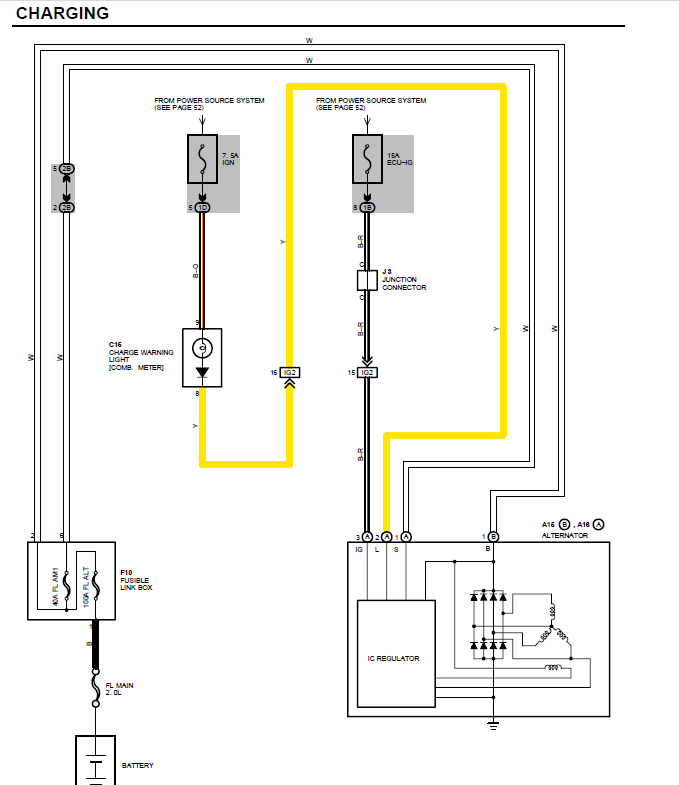
    The image you posted has the same wire colours as below...

    But if you go off the 2WD wiring then you have Pin 2 = Charge Light, which we have decided is not correct

    4WD seems to line up...


    You should be able to trace back with a multimeter The sense wire will go straight to the battery via some fuses, and knowing which fuse feeds the charge light you will be able to find that also

    Do you have a wiring diagram that shows where the wires go from the alternator? i.e. where they terminate to?


    http://www.celicatech.com/imagearchi...d/Charging.pdf
    From here...
    http://www.celicatech.com/imagearchi...ewd/index.html

    But it does show a round plug however, as opposed to flat...


    Cheers
    Wilbo
    Wilbo's Wiki (Includes 2JZ-GTE Wiring, etc! )

    Wilbo's JZA80
    Wilbo's JZZ12

  10. #10
    Junior Member Backyard Mechanic DrNick's Avatar
    Join Date
    May 2008
    Location
    WA
    Posts
    206

    Default Re: 5SFE wiring issues with later model engine

    Quote Originally Posted by wilbo666 View Post
    Pin 1 = L = Charge Light
    Pin 2 = IG = Ignition
    Pin 3 = S = Sense Wire

    Is correct.


    http://www.celicatech.com/imagearchi...d/Charging.pdf
    From here...
    http://www.celicatech.com/imagearchi...ewd/index.html

    But it does show a round plug however, as opposed to flat...
    Uh oh ... But your last diagram that you posted says

    Pin 1.S
    Pin 2.L
    Pin 3.IG

    Is that a celica one or an aristo one?

    The diagram I got is this one

    http://rs95.rapidshare.com/files/245...agram_1993.PDF

    And it has this page


  11. #11
    Is a Chief Engine Builder wilbo666's Avatar
    Join Date
    Sep 2005
    Location
    QLD
    Posts
    3,468

    Default Re: 5SFE wiring issues with later model engine

    Quote Originally Posted by DrNick View Post
    Uh oh ... But your last diagram that you posted says

    Pin 1.S
    Pin 2.L
    Pin 3.IG

    Is that a celica one or an aristo one?
    It's celica, but the diagram indicates it has a round, not flat alternator plug. Which I stated in my post.

    Hence I believe it to only be useful for perhaps the colours and the fuses to help tracing back with a multimeter.

    The links to that diagram are clearly in my post.

    Quote Originally Posted by wilbo666
    http://www.celicatech.com/imagearchi...d/Charging.pdf
    From here...
    http://www.celicatech.com/imagearchi...ewd/index.html

    But it does show a round plug however, as opposed to flat...

    I thought we cleared up what the pin arrangement vs function needed to be already....

    Cheers
    Wilbo
    Wilbo's Wiki (Includes 2JZ-GTE Wiring, etc! )

    Wilbo's JZA80
    Wilbo's JZZ12

  12. #12
    Junior Member Backyard Mechanic DrNick's Avatar
    Join Date
    May 2008
    Location
    WA
    Posts
    206

    Default Re: 5SFE wiring issues with later model engine

    Getting closer now After various other setbacks I tried cranking the car today but had no luck.

    The car is cranking strongly and no strange noises or anything but I put the charger on just to keep the battery topped up all the same.
    It cranks and doesnt even appear to be trying to start. I pulled an injector clip off and there is pulse going there so its getting fuel, but I saw no evidence of a spark when I pulled off a plug lead and held it near ground.

    I checked codes and there was a code 14 which relates to ignition (no IGF signal for 4 revolutions or something along those lines).

    Now that points to Coil / Igniter / ECU - and all of these were removed from working engine. I did test the resistance of the coil and its within spec. I don't know how to test the igniter.

    Will be looking at it tomorrow so if you have any suggestions for the order to look at things that would be much appreciated.

    With regard to the alternator wiring from my first post. I went with this

    Pin 1 = L = Charge Light,
    Pin 2 = IG = Ignition,
    Pin 3 = S = Sense Wire,

    In the off chance that this is wired wrong, would it stop the car from getting spark? I thought that the starting and charging systems were somewhat separate and should not affect each other, but I saw this thread http://www.toymods.net/forums/showthread.php?t=45665 where someone suggested alternator as a cause for no spark when starting.

  13. #13
    Junior Member Backyard Mechanic
    Join Date
    May 2006
    Location
    QLD
    Posts
    352

    Default Re: 5SFE wiring issues with later model engine

    Is the map sensor plugged in?

Similar Threads

  1. TUTORIAL: How to build a 'cheap' 5S-GE motor from 5S-FE
    By bajachris88 in forum Tech and Conversions
    Replies: 9
    Last Post: 21-07-2010, 10:15 PM
  2. MA70 --> JZA70 Conversion
    By Lambolica in forum Engine & Driveline Conversions
    Replies: 119
    Last Post: 09-09-2007, 08:39 PM
  3. Turbos 101
    By WeekendWarrior in forum Tech and Conversions
    Replies: 5
    Last Post: 24-01-2007, 08:23 PM
  4. Toyota Model Codes Explained
    By wagonist in forum FAQ
    Replies: 0
    Last Post: 14-10-2005, 10:47 PM

Bookmarks

Posting Permissions

  • You may not post new threads
  • You may not post replies
  • You may not post attachments
  • You may not edit your posts
  •