Results 1 to 15 of 15

Thread: N/A intake resonance tuning

  1. #1
    Junior Member Domestic Engineer tricky's Avatar
    Join Date
    Sep 2005
    Location
    ACT
    Posts
    628

    Default N/A intake resonance tuning

    I started planning my 18RG--> quad throttle body conversion this afternoon. I just wanna get this information on the site so that others can look over it, add anything I've missed and confirm/refute my theory.

    Basic stats are as follows:

    Engine:18RG
    Bore x stroke: 89.5 x 80mm
    Cam adv duration: 288*

    Goals of conversion: 18R-GE running 4A-GE S/T quads (43mm), resonance tuned. Run by megasquirt.

    Now, firstly, a resonance intake system will optimally have a peak mean intake charge velocity of 300ft/s = 91.44m/s. This velocity is dictated by the greatest restriction in the runner, and can be calculated as follows (assuming 100% VE):

    Peak mean velocity = (Mean piston velocity x piston area)/runner cross sectional area ...(1)

    And mean piston velocity is dependent upon stroke and rpm. I aim for a redline of around 8000rpm, so:

    Mean piston velocity = stroke x frequency x 2 ...(2)

    = 21.33m/s

    Since runner X-sectional area is (re-arrangement of (1)):

    (Mean piston velocity x piston area)/Peak mean velocity, we get A = 1452mm^2,

    So d = 43.2mm, so S/T throttles are a good match.

    Now, since the 18RG is an 8V engine, VE is likely to be crap, so in reality, this velocity would probably occur higher in the rev range.

    Now comes the tricky part... Tuning the runner length. We want the wave reflected by the closing intake valve to reflect and hit the intake valve just as it begins to open again.

    My cams have adv duration of 288*, so they are closed 432*/720*. This equates to 1.2 crank revolutions. Say I tune this for 7500 rpm, the period = 0.008seconds/rev, so our window for reflections is 0.0096seconds.

    The path length of the reflected wave is:

    length = Avg velocity x time ...(3)

    What is the average velocity? Literature states that the reflected wave travels at the speed of sound, but where does the extra energy come from? I'd like to think that the pressure waves travel at the instantaneous velocity of the intake charge as the valve closes. In my case, this is the instantaneous velocity at 75*ABDC, which I don't care to calculate at the moment.

    For speed of sound, l = 340 x 0.0096 = 3.264m, so first harmonic is runner length = l/2 = 1.632m since the wave must travel up then down. Obviously, the first harmonic is inaccessible due to space constraints...

    For a lower velocity, say 75% of mean peak ~70m/s, l = 67cm so l/2 = 33.6cm. In this case, the 2nd harmonic is perfectly useable, with a runner tip to valve length of ~17cm.

    Of course, this is all still partially black art, and to properly implement this, I anticipate dyno time and a telescoping toilet roll trumpet to tune the solution around systemic uncertainties.

    Can anyone shed any light as to why literature states the wave velocity to be the speed of sound? This just seems wrong!
    Nikita the RA23 is almost finished .

  2. #2
    Junior Member Too Much Toyota oldcorollas's Avatar
    Join Date
    Aug 2005
    Location
    sydney
    Posts
    12,496

    Default Re: N/A intake resonance tuning

    hmm... the reflected pressure wave that bounces around IS sound.
    ie a compressing and stretching of the distance between molecules.

    so thats why you use the speed of sound for the speed of the compression wave.

    however, if you want to get picky, the speed of sound changes with gas density, ie at part throttle it will be slower, and at full throttle it will be faster. with forced induction, the speed gets faster again.
    the tricky bit is that as air moves into the runner and is accelerated toward the valve and then stops again, the speed of sound is changing continuously at each point, so it's hard to calculate.
    that help the theory?
    "I'm a Teaspoon, not a mechanic"
    "There is hardly anything in the world that a man can not make a little worse and sell a little cheaper" - John Ruskin (1819 - 1900)

    AU$TRALIA... come and stay and PAY and PAY!!! The moral high horse of the world!

  3. #3
    Junior Member Domestic Engineer tricky's Avatar
    Join Date
    Sep 2005
    Location
    ACT
    Posts
    628

    Default Re: N/A intake resonance tuning

    Yeah, true. I got a bit overwhelmed in a tired state of mind, and stopped thinking in terms of pressure waves, and got stuck in a rut of picturing it as reversion of intake gases...

    With the resonance tuning, it is only really applicable to WOT. Sure, the gas density changes with different throttle angles, but then the waves reflect off the butterfly instead of the open end of the trumpet. Come to think of it, this could be another justification for placing the throttle as far from the valve as possible (the other being a long flow length to let the flow calm after passing the butterfly/shaft).
    Nikita the RA23 is almost finished .

  4. #4
    Junior Member Automotive Encyclopaedia
    Join Date
    Nov 2005
    Location
    Melbourne Victoria
    Posts
    941

    Default Re: N/A intake resonance tuning

    tricky why dont you measure the std inlet with solex length then add say 60mm for a ram tube and go with this ,on the ra40 group c car with fuel injection they used the std efi manifold 1st part and put butterflies on to this and that made power from 3to 8000 rpm just an idea to start you off .im also thinking 43mm will be to small

  5. #5
    Junior Member Domestic Engineer tricky's Avatar
    Join Date
    Sep 2005
    Location
    ACT
    Posts
    628

    Default Re: N/A intake resonance tuning

    I was thinking that getting the rough length by calculations, then a bit of fine tuning on the dyno would be the way to go. You're probably right in that the factory length is quite suited to the power band I'm looking for. I'm thinking about getting an EFI manifold as the starting point, as this has the injector bosses already, so I'd just have to make an adapter plate to the first bit of the manifold. For max power, yes 43mm would probably be a restriction, but it'll still allow for nice midrange. Also they are the throttles I have ATM. I'm on a bit of a tight budget, and this is just an intermediate until I can afford to get a BEAMS 3S to work on I admit, there's only so far I can push an 18RG and retain driveability.
    Nikita the RA23 is almost finished .

  6. #6
    tilting at windmills Carport Converter Ben Wilson's Avatar
    Join Date
    Sep 2005
    Location
    ACT
    Posts
    1,956

    Default Re: N/A intake resonance tuning

    I did a setup for a freinds rally car (4ag), and after computer modeling I wound up with about 1" shorter than the factory runners.


  7. #7
    Just Another Part Time Grease Monkey
    Join Date
    Apr 2006
    Location
    WA
    Posts
    185

    Default Re: N/A intake resonance tuning

    The reflection point from the back of the valve for the harmonics is to the next change in cross-section area. If this is interupted by the butterfly then it might be more complex.

    Absolute kW is neccessary for track cars, I am interested in building streetable cars and while kW is a good talking number, torque is what makes me smile. I say this for others so you know where my focus is based.

    For me carburetors are a compromise since you can't use them with long runners to get to huge torque advantages, since the fuel drops out of the air mix at startup. On efi you can have the longer runners but IMHO the fuel gets injected too late to be completely burned (thus we use catalytic convert) - if the air is moving at 300 to 1500ft/sec the liquid fuel doesn't get too much time to atomise, vapourise and mix with air to form a homogeneous mix. My next conversion will be LPG only so I can mix the vapour in early with the gas and have a completely homogenous mix going into the engine - the longer the runners the better.

    I found an old xls sheet I put together a few years ago when I was looking into NA inlet design (for a V8) that produced high torque at low rpm. It is also suggested that diameter comes into play and so I had planned to use a combination of the two to acheive the best volumetric efficiency. Below is the equation used for the cross sectional area (in) cyl vol (sq in)

    Peak torque rpm = (cross section area)(88200)/cylinder volume.

    With a 43mm butterfly / inlet diameter it comes up with a value of 6700rpm and seems to think a desirable veolicty of the air as 1500ft/sec (or may be 750ft/sec since I can't remember if I considered the 4 stroke cycle - either way the equation constant was a given). Since runner length is basically longer than practical I used another guide line, runner volume = cylinder volume.

    This is so that when the cylinder is filled another full cylinders volume is already in motion on its way behind it (more might sound better but is already the design is hard to fit under the bonnet). Because it is motion it means better volumetric efficiency.

    I once changed an LPG car from using a carb manifold to a efi manifold. After it started we pulled out down the hill normally and it lit up the tyres, which it could never do before especially on a downhill slope - since then for me to get max torque increased length is the key.

    A few years ago I caught the forced induction bug so I am unlikely to put this to good use and instead will focus on other things in customising my 3SGTE into the RA23. First I need to bring it 250km closer to home so I can work on it.

  8. #8
    Junior Member Domestic Engineer myne's Avatar
    Join Date
    Dec 2005
    Location
    sa
    Posts
    629

    Default Re: N/A intake resonance tuning

    "Mean piston velocity = stroke x frequency x 2 ...(2)

    = 21.33m/s"


    89.5 x 8000 x 2 = mm. /1000 = 1432

    Huh?

    Brian, it might still come in handy.
    See, you might think of the engine as a forced induction engine, but really, in 2 ways it isnt.

    1) Before boost
    2) It's only behaving like an engine would if it was a few hundered meters below sea level. Engines dont know they're being forced. They just happen to be designed to work best at a certain pressure.

    So there are 2 ways you could use it.

    1) You could use it to get really good flow down low to get optimum filling before boost. This should result in excellent cruise capabilities and much quicker spool up without effecting the top end significantly.

    2) Treat it as you would any NA engine, but realise that instead of being 14.7psi absolute, it's a bit more. The calculations might vary slightly but I really doubt the physics of it are going to change because of a higher absolute pressure.

  9. #9
    toyota-less Carport Converter skiddz's Avatar
    Join Date
    Apr 2006
    Location
    T'ville, QLD
    Posts
    1,416

    Default Re: N/A intake resonance tuning

    hi

    oldcorollas is right, t the speed of a shockwave changes as the conditions change, in higher temparature it increases due to the gas particles having higher KE

    V=331.4+0.6T (in degrees C not K) where v is the velocity of sound and t is temperature

    if you wanna get really pedantic about it, ur engine temp at idle will be lower than at say 5000rpm, because the combusition is occuring more frequently than at idle, the heat will not disipate as quickly therefore changing your operating temperature.

    under presure and vacum it changes, obviously there is no sound in a complete vacum, and under higher pressures sound travels as though its vibrations in a solid (these arnt pressures u will get in your engine but still good to know), even under the presures of forced induction have a bearing on the shockwave, may be neglegable who knows...?

    please exuse me if i have missed it, but are you trying to shift your powerband up, down, or make it broader? this will have an effect on the runners shape, lenght, and whether or not the butterfly's and diameter of the runners are going to be a large restriction

    best of luck with it all, i'll run your idea past my mech lecturer see what he has to say about it
    Last edited by skiddz; 08-05-2006 at 11:20 PM. Reason: spelling and clarity
    2T out 4A in....

    4A out 3VZ in. 3vzfe rebuild, RWD-ising, and conversion for ta22

  10. #10
    Just Another Part Time Grease Monkey
    Join Date
    Apr 2006
    Location
    WA
    Posts
    185

    Default Re: N/A intake resonance tuning

    Myne - thanks for you comments

    Any advantage of a fancy runner setup on a turbo car I would think to become trivial pretty quick by an extra psi or two into the engine. With FI as soon as the valve starts to open the air/fuel mix is gong to want to get in there because of the pressure, and playing with runner length is only there to try start filling the cylinder immediately rather than wait until vacumn is being developed by the piston moving down. Even so since the inlet ports on my 3SGTE are so huge the runners would not need to be too much longer than planned to get close to the cylinder volume - I will need to take some measurements to find out.

  11. #11
    Junior Member Backyard Mechanic
    Join Date
    Oct 2005
    Location
    South Australia
    Posts
    337

    Default Re: N/A intake resonance tuning

    Quote Originally Posted by myne
    "Mean piston velocity = stroke x frequency x 2 ...(2)

    = 21.33m/s"


    89.5 x 8000 x 2 = mm. /1000 = 1432

    Huh?
    Stroke is 80mm (you used the figure for bore) and the frequency must be in Hz (ie revs per second, not revs per minute)
    If there's one thing I know, it's never to mess with mother nature, mother in-laws and mother freaking Ukrainians

  12. #12
    Junior Member Domestic Engineer tricky's Avatar
    Join Date
    Sep 2005
    Location
    ACT
    Posts
    628

    Default Re: N/A intake resonance tuning

    Quote Originally Posted by RWDboy
    Stroke is 80mm (you used the figure for bore) and the frequency must be in Hz (ie revs per second, not revs per minute)
    beat me to it

    Skiddz, yep, me the eternal physics and maths uni bum indeed knows about the temperature/pressure relation of the speed of sound. I entirely blame my retarded slip of logic (wrt wave speed) on my current penchant for quantum physics... I haven't done classical physics for a while, and in fact, as we speak, I am procrastinating over doing my physics assignment on gaussian wave packets

    My goal with the powerband is to fatten it up in the midsection. Basically, I want it fairly flat from about 5-6000 to redline. There is absolutely no point in tuning for peak hp in a road car, but a fairly flat top end will make a good compromise. To achieve the same goal, I'll probably dial in my cams for 500-1000 less rpm, because my current bottom end balance isn't the best

    Myne, part of the problem with FI cars is the pressure varies much more wildly than in NA cars. You are correct that you simply work with a higher reference pressure, but this, of course, alters the wavespeed (and intensity usually). This is fair enough, what about tuning for an altered wave speed? Again, the fluctuations will be greater than NA, but this is perfectly feasible. As long as you don't go changing your boost levels once you tune the intake, the fluctuations should be no different to the diffence in running an NA car at sea level as opposed to 1000m. Of course, Brian RA23 also has some good points about forced cylinder filling... But intake tuning can be achieved with short runners! Just choose a different harmonic.
    Nikita the RA23 is almost finished .

  13. #13
    Junior Member Domestic Engineer myne's Avatar
    Join Date
    Dec 2005
    Location
    sa
    Posts
    629

    Default Re: N/A intake resonance tuning

    Cheers for the corrections.

    Personally I'd tune the inlet on a turbo engine for 1500-2000rpm.
    Theoretically, the better the filling, the more exhaust, the more boost. Earlier

    You're probably right about the top end not really being worth the effort. I was just making a point because I believe in challenging what I consider 'accepted facts'. It makes people think a bit.

    Since I've been driving my supercharged car, I've come to appreciate low and mid-range grunt. That's why I'd tune the inlet for spool up. It's really a nice experience to have an engine with a broad torque band that doesnt need WOT all the time.

  14. #14
    tilting at windmills Carport Converter Ben Wilson's Avatar
    Join Date
    Sep 2005
    Location
    ACT
    Posts
    1,956

    Default Re: N/A intake resonance tuning

    Funny - I'm beginning to think the exact opposite

    The instant boost starts, inlet tuning is going ot be pretty much irrelevant. The sole reason the inlet manifold is there is to get the air into the motor with the least restriction possible. I'm thinking short, fat runners would be what you are after for forced induction.

    A manifold tuned for 1500RPM will be really restrictive at high revs (particularly with pressurised air). You're probably looking at 800mm or so inlet runners which could also be tricky to fit in the engine bay. As an example, the 4AG I built (pictured above) was tuned for around 5500-6k.

  15. #15
    I'm no Domestic Engineer Steve M's Avatar
    Join Date
    Nov 2005
    Location
    South Australia
    Posts
    614

    Default Re: N/A intake resonance tuning


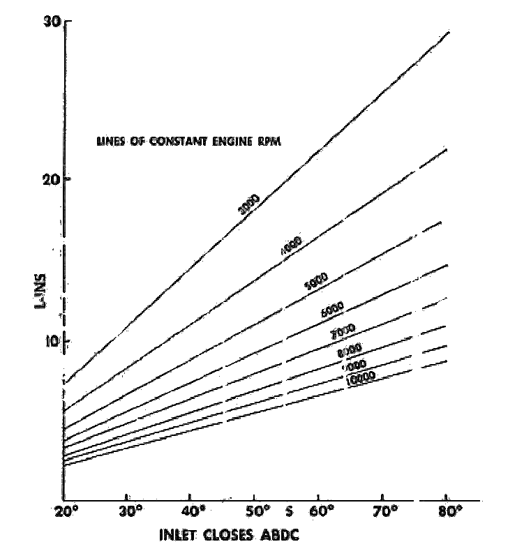
    I'll be referring to this picture. It's more simple for me as my maths ain't that great.
    Intake length in inches is on the Y-axis, valve timing on the X-axis.
    Last edited by Steve M; 09-05-2006 at 04:29 PM.
    Strong like horse, smort like tractor!
    (\__/)
    (='.'=)
    (")_(")

Similar Threads

  1. T, 2T, 2T-B, 2T-C & 2T-G Specifications & Diagrams
    By river in forum Tech and Conversions
    Replies: 67
    Last Post: 29-02-2016, 12:30 PM
  2. Replies: 22
    Last Post: 15-03-2006, 02:24 AM
  3. Underbonet & Intake temps
    By Alchemist in forum Tech and Conversions
    Replies: 47
    Last Post: 09-12-2005, 04:56 PM

Bookmarks

Posting Permissions

  • You may not post new threads
  • You may not post replies
  • You may not post attachments
  • You may not edit your posts
  •