What kit do you have, is it the digital fuel adjuster?
So you have set it up and programmed it correctly?
hey,
wondering if anyone knows about these jaycar fuel cut defeaters or whatever the fuck they decide to call them...I have just put one in mine and it runs like shit to start with on vacuum, it sorta feels like its flooding the motor, and is jerky, it wont even idle smoothly. When driving downhills with no accelerater (engine braking) and then gently applying the accelerator, it spatters and shit, and sounds really abnormal like the motor is being flooded, there is a strong smell of fuel in the air since i have a pin hole in my dump pipe (bad i know) will get it fixed eventually. Also the fuel consumption is pretty bad, and it backfires accasionally off poost. Anyways im thinking that the map sensor reading is being held at 3.7 constanly or whatever the jaycar ones set to. if anyone has had this problem or something simular and knows whats going on please reply with any advice you might have,
cheers,
David
What kit do you have, is it the digital fuel adjuster?
So you have set it up and programmed it correctly?
Are you sure it is installed an working correctly?
This thread sounds similar...
http://www.toymods.net/forums/showthread.php?t=45827
Cheers
Wilbo
its definantely the fuel cut defeater, it came in a pack and cost 20 bucks and all it is, is a pcb board with a few resistors and cathodes and some other weird things, im pretty sure everything is installed right all the resistors are right i double checked them, except the gray thingy im not sure if it is polarised or has to go in a certain way im guessing no?

Oh, haven't seen these before, normally the instructions are fairly good with their kits.
Have you checked on the site for any sort of updates/troubleshooting type ammendments?
Do they need to be programmed/set up on the vehicle at all?
Nigel.
ok just looked at that thread might be getting voltage spikes like you guys say, how do i check if d1 is fucked, coff says if its 1.3v between pin 1 and 12v input it is fucked? i dunno lol seems like a typo in there, im guessing he means it should be 1.3v and if its not replace the d1 diode yeah?
Last edited by chaserbuddy; 12-06-2009 at 10:54 PM.
they just cut off any voltage above 3.9 volts i think from the map sensor and hold it there. just wire it in as far as i know ofOriginally Posted by markiitourerv
Coffee is a dork, ignore his talk of voltage spikes it doesn't make any sense.
Yes one of the diodes was stuffed in his which was causing the 'input' voltage from the map sensor to be connected to ~12V causing his problems.
You have a multimeter right?
Time to get it out and start debugging
The circuit is pretty well just an opamp buffer...
Cheers
Wilbo
i got a multimeter yeah, only thing i know how to do with it is test voltagesOriginally Posted by wilbo666
OK, taken from Silicon Chip here is the schematic and overlay...
http://www.siliconchip.com.au/cms/A_108397/article.html
OK.
Firstly, Coffee's problem was D1 being short circuit. I hope you can see that if you replace D1 with a straight line you are effectively trying to pull 'Map In' to +12V... not so good.
Some points to check.
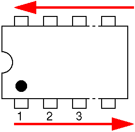
1) Measure the voltage between pin 4 (GND) and pin 8 (+12V) of IC1 (TL072 Op Amp) (see IC numbering pic below to help)
if OK
2) Measure 'Map In' value (engine off, ignition on). 1JZGTE map sensor outputs a value of ~2650mV at normal atmospheric pressure.
if OK
3) Measure the voltage at pin 3 of IC1A. . It should be the same as 'Map In'.
if OK
4) Measure the voltage at pin 1 of IC1A. It should be the same as 'Map In' & pin 3 of IC1A
if OK
5) Depending on the outcomes above we will move on to more testing from there


Have you wired it in backwards ?
11.72 @ 116.7mph = Quickest Stock Turbo Jzz30 series SoarerAnd 1st into the 11's
WOOOT!!!
Still going good
http://www.youtube.com/watch?v=tc_7aRUGshw
sorry i originally checked d1 and it seemed fine but when i went to check it again it read 9.6v just by connecting a voltmeter to either side of it. and D2 read 2.6v by doing the same i dont know if that is right? you tell me...
1) 12V
2) Map in 2.65v
3) 2.65V
4) 2.65V
the jaycar instructions say that voltages between pin 4 and pin 8 on ic1 should be +5.6V but its more like 13.9v with the engine on idle, and pin 5 on ic1 is 3.9V like the jaycar instructions say...
Last edited by chaserbuddy; 13-06-2009 at 02:51 PM.
Doing well then. The voltages you have measured rule out a lot of things being broken / incorrect
Next
6) Measure the voltage at pin 6 of IC1, should be 'Map In' voltage
if OK
7) Measure the voltage at pin 7 of IC1, it should be ~300mV less (the voltage drop across the diode) than 'Map In' when 'Map In' is less than the voltage at pin 5 of IC1. IC1B is configured as a Comparator, when the voltage at pin 6 is bigger than that at pin 5, the output connects to GND...
if OK
8) Measure 'Output to ECU' it should be 'Map In' when 'Map In' is less than ~3.9V
Cheers
Wilbo
6) volt at pin 6 = map in voltage
7) pin 7 of ic1 is 11.68v, (pin 5 of ic1 is 3.9v)
8) output to ecu is 1.44v when running and map in is 1.3v ( on ignition the maps are simular same 2.61v input 2.62-2.63 on output)
It sounds like it is working fine then...?
Cheers
Wilbo
Bookmarks