Page 2 of 3 FirstFirst 123 LastLast
Results 16 to 30 of 33

Thread: engine cranking amps and circuit breakers

  1. #16
    Your mum is a Conversion King TERRA Operative's Avatar
    Join Date
    Mar 2007
    Location
    Chiba
    Posts
    2,232

    Default Re: engine cranking amps and circuit breakers

    More resistance will mean the current will still try to flow and can heat the cable up.
    It's the way fuses work, the link heats up with overcurrent and melts to break the circuit.

    Let us know the diameter of the copper in the cable and I can work out the current draw the cable can handle.

  2. #17
    Founding ****** Automotive Encyclopaedia Mos's Avatar
    Join Date
    Jul 2005
    Location
    NSW
    Posts
    1,157

    Default Re: engine cranking amps and circuit breakers

    Quote Originally Posted by cambelt1
    And if you have a manual car and run out of petrol in the middle of a intersection and you think hey, i can crank my way across using the statrter . Untill the fuse blows because of the extra load of moving the car on the starter .
    I know this is a highly unlikely situation tho and i have never needed to do it.
    I have done this (not quite an intersection though) and yes it would blow, but that's why it would be better to use the contactor to short out the fuse over choosing a fuse rating that wouldn't blow [ever].
    (It's also why my battery is half a foot away from my engine ).

    Quote Originally Posted by adamaw11
    I've used welding cable for the relocation, relatively thin compared to what people seem to use but its adequate.
    Depends which welding cable.... Narva has 6 sizes, and if you go by their ratings any of them would be "adequate"

    Quote Originally Posted by adamaw11
    Will more resistance in the battery cables cause LESS current draw or more?
    LESS!

    Quote Originally Posted by TERRA Operative
    More resistance will mean the current will still try to flow and can heat the cable up.
    Well, not as much current will try to flow because there will be less Voltage to pull the current... and every cable will heat up [a bit].

    Quote Originally Posted by TERRA Operative
    Let us know the diameter of the copper in the cable and I can work out the current draw the cable can handle.
    What calculations do you use?

    Quote Originally Posted by TERRA Operative
    I have measured my AE101 4AGZE to pull exactly 225A on cranking.
    Hmm, interesting. The continous current on the 1G-FE was around 140A. Haven't measured the 1UZ or the peak current...

    Quote Originally Posted by TERRA Operative
    I'm running 0 gauge cable and a 200A ANL fuse in a Stinger fuse holder for my relocation, and it's been running with no problems at all for almost a year.
    Good to see some of the theory works
    Quote Originally Posted by TERRA Operative
    So if I pull 300A, it'll last for 7 seconds according to that chart above.
    At least in theory


    Now more crap, but if you're bored already, skip to the last line
    When choosing a cable some things to consider are heat and voltage drop. Can your powered instrument tolerate a voltage drop? Can your cable handle more heat?

    Conductor current capacity has various standards of measurement - I don't know what they are specifically, but they are not all same.
    For example Jaycar rates an 8 Gauge, 7.5mm^2 cable at 56Amps, however Narva rates a 7.7mm^2 cable at 100Amps at a 60% duty cycle. Narva also rates a 4.6mm^2 cable at 50Amps at 60%dc.
    As another comparison, Jaycar 4G 21mm^2 cable is 110Amps, Narva 16mm^2 welding cable is rated at 150 at 60%dc or 215Amps at 30%dc for 5 Minutes (I'm guessing they stop for a smoko after 5 minutes).

    The main difference is that Jaycar rates those cables with a continuous load, whereas welding cables don't get used with a continuous duty cycle, giving the cable time to cool down.
    Cables with teflon insulation and other high temperature insulators can be rated at higher currents in certain situations as they can take more heat before the insulator stops insulating (ie melting).

    A rule of thumb is that every square millimetre of copper can handle around 10Amps continuously. So an 8mm^2 cable should be able to handle around 80Amps continously.
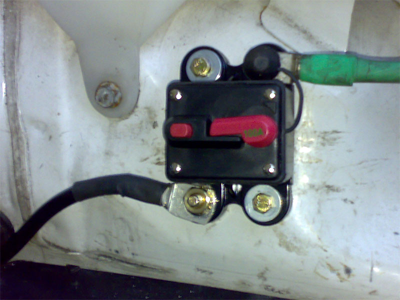
    For instance Toyota used a 7.9mm^2 cable on a circuit fused with a 100Amp fuse (which normally would only see about half of that current continously).

    And things like jumper leads are another joke - a 200A jumper lead set has less copper than a 25A Jaycar cable. They heat up for a reason

    The thinner the cable, the higher the resistance. Extra resistance means LESS current will flow. Less electrical energy will get to the starter.
    Everything has resistances, even batteries. The larger the resistance, the larger the voltage drop across that resistance at a specific current - ohm's law - V=IR. The larger the voltage drop, the larger the power dissipation across that resistance - P=VI - the object is to minimise voltage drops - you can't get rid of them completely.

    By using a thicker cable you are minimising the effect of the voltage drop of the cable. The longer the cable, the larger the resistance, obviously, so it makes a bigger difference when you install your battery in the boot.

    Ever noticed some ground leads from the battery to the chassis are relatively thin compared to the starter cable? The reason is that the cable is very short - maybe 6 inches - so the voltage drop across that cable is relatively low compared to the positive side, so increasing its size has a negligible effect.

    In theory the resistivity of materials is more or less fixed and resistances cable be calculated.
    Copper is 1.72x10^-8 ohm-metres at 20 degrees C. The resistivity divided by the cross sectional area of the conductor, multiplied by its length, gives the resistance.
    So taking our Jaycar 4G cable at 21mm^2, in theory it will have a resistance of 0.000815 ohms per every metre. A ten metre length of this cable will have 0.00815 ohms
    In practice, the data tells us the 4G cable has a resistance of 0.00097 ohms per metre.

    Practically speaking the 4G cable will give a voltage drop, per metre, rounded, of 0.1V at 100A, 0.2V at 200A, 0.3V at 300A, etc.
    Using the Narva 35mm^2 welding cable (rated at 250/355A) these voltage drops would be roughly halved.
    Does it make a difference? Sometimes it does, sometimes it doesn't.
    A 5 metre length of 4G cable can produce a 1.5V drop at 300A (and 450W of heat!! but only for a very short time ) More realistically though, the 0.5V drop at 100A would not make a lot of difference unless your battery is struggling - even a good battery will drop more than 0.5V on cranking.
    The voltage drop on an alternator cable doesn't really matter, because the regulator compensates for it anyway - it increases the output voltage to make up the voltage drop at higher currents.
    Obviously much smaller currents are involved, but small voltage drops on sensors wiring can have big effect - eg map sensor reading.
    On a starter motor, it will only really have an effect with a crap battery or some other problems like loose connections.

    Mos.

    PS. I'm not bored enough to calculate the temperature rise
    Admin, I.T., Founding Member, Toymods Car Club Inc.
    2000 IS200 Sports Luxury 1UZ-FE VVTi, 1991 MX83 Grande 2JZ-GTE (sold)

  3. #18
    Your mum is a Conversion King TERRA Operative's Avatar
    Join Date
    Mar 2007
    Location
    Chiba
    Posts
    2,232

    Default Re: engine cranking amps and circuit breakers

    I use AS3008.1998 (I thinkit's 1998, the latest anyway) to calculate current capacity and voltage drop.

    Although I'll need to know cable length and where it's run to get it dead accurate.

  4. #19
    Founding ****** Automotive Encyclopaedia Mos's Avatar
    Join Date
    Jul 2005
    Location
    NSW
    Posts
    1,157

    Default Re: engine cranking amps and circuit breakers

    Have you got excerpts or something you can post? I'm curious how they state it, but not enough to buy the standard....
    Admin, I.T., Founding Member, Toymods Car Club Inc.
    2000 IS200 Sports Luxury 1UZ-FE VVTi, 1991 MX83 Grande 2JZ-GTE (sold)

  5. #20
    Gary Motorsport Inc. Too Much Toyota takai's Avatar
    Join Date
    Oct 2005
    Location
    Victoria
    Posts
    5,543

    Default Re: engine cranking amps and circuit breakers

    I use a 120A fuse and 4AWG cable for my starter, but its isolated from the rest of the system (due to how the car is wired for CAMS).

    I have a second 4AWG 80A fuse for the rest of the car (bar alternator which feeds back through the starter)
    -Chris | Garage takai - Breaking cars since 1998
    Sparky - AE86 IPRA Racer | RZN149 Hilux - Parts and Car Hauler
    I never saw a wild thing sorry for itself. A small bird will drop frozen dead from a bough without ever having felt sorry for itself. - D.H.Lawrence

  6. #21
    Your mum is a Conversion King TERRA Operative's Avatar
    Join Date
    Mar 2007
    Location
    Chiba
    Posts
    2,232

    Default Re: engine cranking amps and circuit breakers

    Quote Originally Posted by Mos
    Have you got excerpts or something you can post? I'm curious how they state it, but not enough to buy the standard....
    Yea. I'll sort through the relevant bits and post it up.

    It is more for AC 240 and 415V but ohms law is ohms law...

  7. #22
    Junior Member Chief Engine Builder Classique71's Avatar
    Join Date
    Sep 2005
    Location
    Victoria
    Posts
    3,425

    Default Re: engine cranking amps and circuit breakers

    If it hasnt already been posted - this is what you need to get it all hoooked up ..

    http://www.projecta.com.au/catalogue/cid/35/asset_id/84


    Fused battery terminal from projecta ..
    Saphira - ST205 Celica GT-FOUR Group A NZ No:1/4
    "Mongrel Garage - back on Aussie soil! "

  8. #23
    ethanol sniffing Backyard Mechanic adamaw11's Avatar
    Join Date
    Dec 2005
    Location
    Qld
    Posts
    328

    Default Re: engine cranking amps and circuit breakers

    Well I had a closer look at my battery relocation cable, and it says 25mm squared on it.
    measured the copper inside the insulation and its about 6mm cross section diameter.
    I guess that should carry 250amps easily right? (based on that rule of 10amps per mm squared)

    I've ordered a 200amp circuit breaker off ebay, its one of those cheap ones that comes from hong kong.
    http://www.toymods.org.au/forums/showthread.php?t=83259
    '88 A.D.M aw11 '98 4age 20v blacktop
    NA: 14.745@150kmh at willowbank. On E85 with 6psi boost: 13.573@165kmh. ~8psi: 13.187 @169.9kmh. >10psi: 12.9 rod fragments @ 174mm holes in block
    daily: '93 ae101 Levin coupe. Motorbike: '09 Suzuki GSR600: 12.358@179kmh at Willowbank

  9. #24
    Gary Motorsport Inc. Too Much Toyota takai's Avatar
    Join Date
    Oct 2005
    Location
    Victoria
    Posts
    5,543

    Default Re: engine cranking amps and circuit breakers

    At what SWL though, it might do 250A but how close is it to the upper limit?
    -Chris | Garage takai - Breaking cars since 1998
    Sparky - AE86 IPRA Racer | RZN149 Hilux - Parts and Car Hauler
    I never saw a wild thing sorry for itself. A small bird will drop frozen dead from a bough without ever having felt sorry for itself. - D.H.Lawrence

  10. #25
    Junior Member Chief Engine Builder Classique71's Avatar
    Join Date
    Sep 2005
    Location
    Victoria
    Posts
    3,425

    Default Re: engine cranking amps and circuit breakers

    hence the link i posted .. May not be suitable for some - but its well suited for street car applications and not mind boggingly complicated or expensive

    Ill give feedback on it asap , if anyone wants to know ( it'll be kicking over my st205 , off a pc680 odyessy battery , rear mount battery setup )
    Saphira - ST205 Celica GT-FOUR Group A NZ No:1/4
    "Mongrel Garage - back on Aussie soil! "

  11. #26
    Founding ****** Automotive Encyclopaedia Mos's Avatar
    Join Date
    Jul 2005
    Location
    NSW
    Posts
    1,157

    Default Re: engine cranking amps and circuit breakers

    Quote Originally Posted by takai
    At what SWL though, it might do 250A but how close is it to the upper limit?
    SWL - safe working load?

    I guess it's kind of like a piece of steel but not quite. Above a certain load a piece of steel will exceed its elastic limit and deform or damage.

    A conductor doesn't really behave the same way - I guess the only damage you can really speak of is the insulation melting off, and that will be a function of heat; and heat is a function of the amount of energy requiring dissipation which is the power multiplied by the time that this energy is being dissipated. I suppose you could call it "load" but it will be a combination of current and time. The same amount of energy can be delivered quickly or slowly, corresponding to how much current you're asking the cable to handle, and for how long.

    IE it might take 1000Amps for 1 second before it heats up enough to melt the insulation. Or it could take 500A for 20 minutes before it melts the insulation. It could take 250A for 100hours... Yes the cable will heat up, eventually the insulation will melt, after that eventually the copper will melt.
    Estimates for worst case scenarios are all calculable if you know the amount of copper, the time, the current and assume there is no cooling effect, but I'm just picking numbers to illustrate the point.

    For the purposes of the application - ie starter cable - even 500 Amps for the 2 or 4 seconds that the starter is cranking wont do diddly squat to damage it - let alone you be able to feel the temperature rise - so pretty much *nothing* you could throw at it during normal operation would cause it damage (perhaps a direct short would melt it, but I don't know what sort of times we're talking about at the currents that a battery can deliver).

    Notice that I haven't even mentioned voltage drop - why? because the cable does not care in the slightest what the voltage drop across it is.

    So in terms of being close to an upper limit of destroying a cable, 250A for 5 seconds through a 25mm^2 cable won't be anywhere near close (otherwise 200A jumper leads would evaporate in use....).

    Mos.
    Admin, I.T., Founding Member, Toymods Car Club Inc.
    2000 IS200 Sports Luxury 1UZ-FE VVTi, 1991 MX83 Grande 2JZ-GTE (sold)

  12. #27
    Junior Member Conversion King Drifty Midship's Avatar
    Join Date
    Jan 2006
    Location
    北海度
    Posts
    2,691

    Default Re: engine cranking amps and circuit breakers

    I got a 100amp one. $17 off ebay on my AW11 with a Deka Etx 16 (275 CCA).
    Mine will trip on about 10-12 seconds continuous cranking... but gives me no problems as long as the engine is starting properly.
    For testing or diagnosing engine problems or emergencies I keep a small bolt and nut and leccy tape in the glovebox I just remove the leads and bolt them together, leccy tape em up to temporarily bypass it.

    AW11 - 1988 Red ADM 4AGZE conversion +
    MZW11 - 1987 Track car - "Ag-Spec Racing 1" - 1MZ powered AW11
    ST246 - 2002 Caldina GT-Four 'N-Edition'
    MS65 - 1973 Bash Car bash.skyracing.tv/

  13. #28
    Building Corollas Chief Engine Builder Cuzzo's Avatar
    Join Date
    Oct 2005
    Location
    NSW
    Posts
    4,626

    Default Re: engine cranking amps and circuit breakers

    Quote Originally Posted by Drifty Midship
    I got a 100amp one. $17 off ebay on my AW11 with a Deka Etx 16 (275 CCA).
    Mine will trip on about 10-12 seconds continuous cranking... but gives me no problems as long as the engine is starting properly.
    For testing or diagnosing engine problems or emergencies I keep a small bolt and nut and leccy tape in the glovebox I just remove the leads and bolt them together, leccy tape em up to temporarily bypass it.

    Ok i had those exact ones.

    Had one on the alt line and one on the starter line. The starter would always trip.
    secondly it will fail soon. I had them for about 1month and it flicked the switch but didnt cut the power. The other one did the opposite and the switch wouldnt stay on meaning the power was always cut.

    Good luck!
    KE30 4agte - Bullet - Rick Rolled
    UZX83 1UZ W58- Cruiser - Tow Car - Fun Car
    Quote Originally Posted by -GT- View Post
    You had an oil and plastics engine bay fire, with flames that reached at least to the roof - of course shit got hot, it wasn't burning jiffy firelighters back there.

  14. #29
    Junior Member Conversion King Drifty Midship's Avatar
    Join Date
    Jan 2006
    Location
    北海度
    Posts
    2,691

    Default Re: engine cranking amps and circuit breakers

    Had mine for about a year now.
    Don't use the adub very much tho'.
    When she blows will upgrade.
    AW11 - 1988 Red ADM 4AGZE conversion +
    MZW11 - 1987 Track car - "Ag-Spec Racing 1" - 1MZ powered AW11
    ST246 - 2002 Caldina GT-Four 'N-Edition'
    MS65 - 1973 Bash Car bash.skyracing.tv/

  15. #30
    Gary Motorsport Inc. Too Much Toyota takai's Avatar
    Join Date
    Oct 2005
    Location
    Victoria
    Posts
    5,543

    Default Re: engine cranking amps and circuit breakers

    Quote Originally Posted by Mos
    SWL - safe working load?
    Safe Working Limit. Similar concept, just thinking about the headroom needed.

    25mm^2 does sound like a whole lot, but im not sure how its really measured, since my 120A 4AWG cables are marked 40mm^2
    -Chris | Garage takai - Breaking cars since 1998
    Sparky - AE86 IPRA Racer | RZN149 Hilux - Parts and Car Hauler
    I never saw a wild thing sorry for itself. A small bird will drop frozen dead from a bough without ever having felt sorry for itself. - D.H.Lawrence

Similar Threads

  1. Aftermarket engine management and injectors
    By benjamin in forum Tech and Conversions
    Replies: 14
    Last Post: 14-05-2006, 02:05 PM

Bookmarks

Posting Permissions

  • You may not post new threads
  • You may not post replies
  • You may not post attachments
  • You may not edit your posts
  •