
 Reply With Quote
i think ive designed a entirely pneumatic way to control the bypass TB. im putting together a lengthy reply with it now. plenty of cad diagrams
seems fool proof but i will need constructive critisism to explore every scenario!


im sure the HKS would perform but the driveability for daily use would be questionable. and ill guess it uses a oneway valve too - not the best in my opinion.
hello
i think ive designed a entirely pneumatic way to control the bypass TB. im putting together a lengthy reply with it now. plenty of cad diagrams
seems fool proof but i will need constructive critisism to explore every scenario!
hello
well as previously stated here is a prototype for a pneumatically controlled bypass TB.
diagram 1. we can see the general jist of the system. it will be utilising 2 pressure driven actuators, similar to that on a turbo wategate actuator. actuator (1) will be sealed on one side only. however, actuator (2) will be sealed from both sides so it can move either way and pressure/vacuum can be applied to either side of the piston.
a couple things to note;
1. Actuator (2) will not move the shaft in any direction if the pressure on either side of the piston/diaphram is equal. that pressure can be anything as long as its equal.
2. there is a spring that constantly pulls the bypass TB closed.
3. they are sectioned views of the actuators
sorry for the lack of contrast in the images (damn imageshack). if they are hard to see, copy them to paint and invert the colours
okay here is the general overview.
and a close up of the new design
now ill go through the scenario of cruising along with the SC on, and then bascially floor it to redline
so here it starts, cruising along the road at a constant speed. when cruising there is vacuum in the inlet manifold so it will be naturally pulling the bypass valve open, via actuator (2). the SC is also on which means its making ~6psi boost. because of the high pressure in the section between the 2 TB's, (remember driver TB is nearly closed whilst cruising) the actuator (2) will naturally also want to open the bypass TB.
so this should self regulate. this setup will also be handy during backing-off of the throttle - pressure spike will cause bypass TB to vent pressure (BOV style). if the bypass is open, the air pumping through the SC will basically do 'laps' of that section of the pipe . anyway....here is the diagram for that scenario.
okay, now i put my foot flat to the floor. the turbo isnt making any pressure (yet) and the SC is on. now because the driver TB is wide open there is no pressure difference in actuator (2), this will have NO effect on how much the bypass TB is open. the other factor is actuator (1), but because there is only ATMO pressure in the piping where it's connected, it wont change the bypass TB position either. so, the only factor affecting the position of the bypass TB is the spring....this will have the effect of snapping the bypass TB shut....perfect

so this diagram illistrates the above text.
so the next part of the WOT journey is that the turbo begins to make some boost. now because the driver TB is still open , actuator (2) is still having no effect on the bypass TB. BUT, there is pressure beginning to build in actuator (1) so once the force of this actuator overcomes the spring, the bypass TB will open to allow LOTS of air to enter the engine.
so the next 2 diagrams show the transtion of this. pretty well self explanitory. one thing to note though; when the SC is on and both TB's are fully open, the turbo air flow will find the easiest route to the engine so the pressure should be equal on each side of the SC - and so impose minimal drag on the engine
so far i cant see any bugs with this setup. the SC would be wired to bascially switch off after 3 seconds of X amount of vacuum and then cut in with X amount of vacuum.
there may also be something wired into the bypass valve to fully open it when the SC is off.
having the system completely pneumatic might be easyier to get the system up and running and give me time to learn more about electronics so i can implement the electronic system
constructive critisism on this would be great
cya
brett
hello
Very good diagrams and nice idea. But I have my doubts to if it will work all that well. Well it will work, but won't be optimal. I am thinking in terms of air flow in each flow path and the pressure differences (PD) in them.
Before the BPTB (bypass TB) opens the SC will magnifying the boost from the turbo. Just say the SC makes 10psi. This means that there will always be 10psi more after the BPTB than before it when its closed (when you floor it) so add 10psi to what ever is coming from the turbo. This means there can't be an optimum time to switch over. The pressure difference across the SC should be close to zero before a smooth change over can be made. If there is more pressure behind the BPTB than before it, when it opens air will flow backwards towards the turbo and back toward the SC in a loop. You will see a reduction is boost because as the BPTB opens, the higher boost pressure behind the BPTB will bleed away from the engine and flow back into the lower pressure zone created by the turbo.
Once it is fully open the SC will be redundant as you say and could be switched off. You could just have a pressure differential switch to switch the SC off when the PD across the SC is close to zero.
Hmm. Just pondering. To avoid this PD problem in your system you could tune it so that as soon as ANY boost is created by the turbo the BPTB starts opening slightly to act as a boost control measure like a normal wastegate. This will eventually equalize the PD across the SC.
Scenario: SC makes 10psi and BPTB actuator is set to control boost to 10psi by bleeding air back to the SC intake as the turbo comes on boost. Turbo starts to make boost say 0.5psi but has a over all wastegate setting of 15psi. Boost after the SC will be 10.5 psi when you add the boost from the turbo.. Because the BPTB actuator is set to 10psi, it will open and bleed air back to the SC. (a PD of 10 psi exists there) As the turbo spins harder and harder the BPTB will have to open more and more to keep boost at 10psi. As the turbo makes more boost the PD across the SC will get lower. Eventually it will be open all the way and as boost from the turbo rises above 10psi the SC will be redundant and can be switched off via pressure switch. This point in time is exactly when the turbo starts to out perform the SC. Boost can continue to rise to 15psi through the open BPTB.
This should provide seamless operation, but I think the system I described will be easier and less complicated. I really want to try this on my 2JZ
Last edited by 2JZR31; 26-07-2006 at 10:06 AM.
great effort with your reply
longer reply coming with more diagrams soon
hello
so ive modified my diagram to something along the lines of what your saying (i think)
i feel that this is definately a better setup. although last night i was beginning to come along the lines of a single actuator
anyway here is the new diagram
now with this, it should be possible to just use a turbo wastegate actuator to control the bypass. and to prevent bypass valve creep, a bleed valve or boost controller could be used
so yes, as you said, the pressure in the section between the 2 TB's will be regulated to stay at 10psi (SC pressure) until the turbo has equalised the pressure EVERYWHERE. then when everything is equal, but more than 10psi, the bypass will just go wide open
now what i was also thinking of having was one or two bosch type bypass valves which open under vacuum. so when the car is just cruising along (on the highway) there is vacuum so these valves will open and allow air to bypass the SC and bypass the bypass TB (seeing as its closed) . these would be plumbed basically parallel to the SC.
then to drive it the SC, it would be hooked up to the ECU (aftermarket
pretty straight foward setup on most ECU's
so your cruising along, there is vacuum so the bypass valves are open and providing all the air, SC is off and then you put your foot down. the pressure begins to drop so the bypass valves are just about to close due to vacuum drop but before that happens the ECU cuts the SC in and BAM - sufficient air is getting to the motor
Last edited by brett_celicacoupe; 26-07-2006 at 10:25 AM.
hello
Sounds a good
I still think the version I described would be more simple and easier to implement plus it easily allows the intercooling of the SC and turbo. Any drawings I make would look like shit compared to yours! Did you pay for that program? If you can send it to me at [email protected]
the only reason i op'ted to have the SC non - intercooled is to get it VERY close to the engine and so reduce the time it takes to fill all the piping and intercooler
after all, the driving force in this setup is to have good low-down throttle response from the SC. a little bit of heat never hurt anyone
hello
Ok. Should be sweet. I was thinking of running the SC to its absolute limit in my proposed setup on a 2JZ so the air coming out would be pretty hot. Plus I'm not sure if the air temp sensors would be quick enough to react to such large and quick variations in inlet temp. I think keeping trying to keep temps stable would have its advantages...
And where did you get that programMS paint sucks
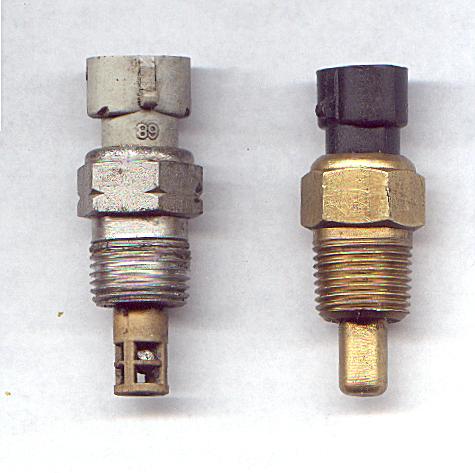
open cage airtemp sensors (as found in V6 commodes oddly enough) will have fast enough response for turbos.
On left is open cage ir temp sensor, on right is a coolant sensor
(pic courtesy of www.msefi.com)
A few early installations using the open-cage MAT sensor experienced vibration induced failure of the sensor. The thermistor bulb is supported only by two thin wire legs. These can apparently fatigue and break when installed in high vibration environments, such as occurs when you screw it directly into an intake manifold. Several people solved the problem by "potting" the legs of the thermistor with O2-sensor-safe silicone (most silicone sealer/adhesives destroy O2 sensors, so pay attention!), squeezing it down inside the sensor body but leaving the bulb exposed
program is autoCAD
from what Mic* said, his 1GGZE supercharger clutch would slip after he put a smaller pulley on it because of more load from more boost.
so that only really leaves the options of having the SC running full time or increasing the size of the crank pulley
hello

But you say you opted not to have an IC?Originally Posted by brett_celicacoupe
Toyota used top mount water to air ICs on their performance turbo cars in order to keep this volume low, but is mainly due to the pressure drop and turbo spool up.
The query is partly about the time to PRESSURISE the inlet BEFORE the throttle.
Once the SC is making pressure [which is instant while the SC is running] the time to raise the pressure before the throttle is in fractions of a second. The pressure wave travels at the speed of sound! If less than atmospheric [vacuum] this speed slows and conversely if boost is avbl the speed of the pressure front is greater. This speed is around 340m/s.
If you consider VOLUME and let's say 1000RPM a 2L NA engine at 100% efficiency will consume 1000L/min. The SC should be able to supply 1400L/min with a 1:1 drive and 100% efficiency. That's about 23L/s at idle or 6.5L/s over what a NA engine would consume. The volume needed to be filled if a perfect vacuum existed is the volume from the throttle to the valves. This is typically around 2-3L or around 0.15s at worst. This is also why a supercharged or turbocharged inlet manifold is smaller than the NA version. As SC is fairly linear in its delivery, the time will be less at higher RPM.
Has anyone considered running them in parallel rather than in series?
That is, you have common air intake; and the common outlet has a single flapper type valve where the outlets meet. Pressurised air operates the valve with the help of an over centre spring so that whichever outlet has the higher pressure shuts the other off. The SC can be shut off whenever the TC pressure is higher than a set value or dedicated load-rpm points to switch
...................SC
................../.....\
.cold air box........valve - IC - throttle - manifold
..................\...../
....................TC
.
I saw this setup on an RA60 where the guy had got a 22R-TE and mounted an unknown SC.
Last edited by Rcubed; 26-07-2006 at 11:56 PM. Reason: correcting some data
im not sure if people already know this or not but BD4s hat a twin blower kit from HKS for the 4agze they do the kit for roughly $9000 drive in drive out evereything is hks including the turbo being a hks T0(big turbo for a 1.6) and the hks high mount turbo manifold i have a very old issue of fast fours containing 10 pages worth of information about it an how it works
They havent made that kit in a VERY long time.
Try this then. I modded a late model SC12 pulley to fit on my SC14 and no problems getting 18-19psi on the boost gauge! Belt slip is my problem, or rather frequent belt re-tensioning.
Funny this, as the SC14 clutch is much larger in both surface area and diameter.......
Cheers, Nick
== 4AGZE SC14 Supercharged ==
Now flogg'n the SC14 @ 18psi....
 Posting Permissions


Bookmarks