


 Reply With Quote
If I was to post up the CAL file and a LOG of the car running could someone a bit better versed than I have a squiz and see if
something in the calibration could be the issue?
Cheers Toymodders


Righto, so I bought one of them fandangled plastic rectangular brain boxes from 'Merica around the time they were released,
basically it was well priced with our dollar being wicked strong at the time, claims it can do some rather cool shit for the
money and also that it was compatible with both Hall and Mag/VR inputs. apples methinks...
http://aemelectronics.com/?q=product...s-4/universal-
programmable-ems-4
So wires up the loom, connects the laptop, friendly user interface with presets for the injectors and 1nzfe COP, set my firing
order (forgot to wire plugs and injectors in firing order, no biggie)
The calibration was setup with some help from a friend who had has done this ecu on a 1uzfe in batch fire.
24+1 4agze CAS with one home reluctor for the dumb fire ignitor removed and the sensor polarity reversed to rising
edge that the ECU requires.
Got the thing fired up and ignition locked in at 10 degrees BTDC
Took it down to my mates shop and strapped it on the dyno and rolled it up gently just checking things over, and it
pinged at anything over about 3000 RPM.
Had a look with the timing light and the ignition locked at 10 degrees BTDC and at around that 3000 RPM
mark the timing jumps up what I would guess is 30 degrees or one full fuel/spark tooth.
Thought the issue might be noise as we had already added some filtering as my mate had encountered noise issues
on the 1uz he did.
A couple of pull down resistors with some capacitors in parallel that pull down to earth, I feel it's fairly average to have to do this, but it's what they officially claims needs to be done, now knowing this I would have avoided this ECU...
http://aemelectronics.com/?q=forum/e...ook-here-first
Went all the way to a 200 Ohm resistor and the signal basically disappeared and all it seemed to do was make the
issue happen a bit later in the rev range.
I think I ended up leaving a 500 ohm setup in there.
Wiring is the shielded quality stuff supplied with the loom, it does run parallel in the loom with the ignition wiring but
it's only 5v triggering so I cant see how that is a problem, I probed the output of the cas with a scope and the
signal looks as it should to me...
Anyone have any experience with this ECU or any ideas for that matter?
Seems to me the internal circuit of this ECU that converts the sinusoidal signal to an ON or OFF square like a hall is
just not up to the task of this dirty Mag output, people have run them on 3sgte, isn't that basically the same CAS?
Starting to not be comfortable with the idea of losing a clear signal and getting massive ignition advance on boost
losing an engine.
That and the frigging thing wont turn on sometimes, and get this, the official fix is to assign a password so the ecu
boots up differently and doesn't "freeze", still does it, and I've checked for any backfeed from anywhere not letting
it turn off correctly, which is their other suggestion.
Anywho. I'm out of ideas, apart from basically putting the equivalent of a drop saw blade on the crank with a HAll
sensor and just using the home signal in the CAS or..
Just getting a Haltech like I should have in the first damn place and repinning the loom to suit that.
Experiences with Haltech sprint 500 on 4agze CAS anyone?
If I was to post up the CAL file and a LOG of the car running could someone a bit better versed than I have a squiz and see if
something in the calibration could be the issue?
Cheers Toymodders
Hi mate,
That sounds like a typical reluctor issue. At this stage I would not go blaming the ecu or even noise.
I would reverse the wires into the ecu i.e. change the one going to signal to earth and vice versa. May then have to change the ecu to falling edge.
Cheers,
Jason
3TC Compound Turbo 1976 TA23 - Members Ride Thread HERE
479RWHP on 50psi and 70psi hasn't broken her at the track!
Hi NME
I had to change the polarity at the reluctors inside the CAS as they have a shared earth, the output from what I can see is rising edge now, can anyone confirm?
And the input to the ECU has been checked and is correct and the settings are MAG Rising Edge on both crank and cam signal, the manual says it has to see rising edge for reluctor type?
Are you saying to try falling edge?
Im guessing the issue is it gets confused about which significant edge it is counting,?
A reluctor will increase the timing when wired one direction and will stay fairly steady when wired the other way.
What are you seeing again?
Cheers,
Jason
3TC Compound Turbo 1976 TA23 - Members Ride Thread HERE
479RWHP on 50psi and 70psi hasn't broken her at the track!
Ah that makes sense, as the RPM increases the signal lags or stretches?Originally Posted by NME308

I was referring to what I was seeing from the oscilloscope, as in being a rising edge signal, as per what AEM requires.
So if this ECU cant count a significant falling edge properly and this CAS wont give a steady output with polarity reversed I may not be able to make this arrangement work.
Haltech will do both falling and rising for Mag reluctor type, so with the CAS rewired to what it was designed for, falling, all should be good?
..
I just want to be clear with what the issue may be before I commit to banging some bannanas out of the wallet on a new brain.
Ok so I have come in from the shed for dinner and downloaded the AEM software as i have not seen an ecu which doesn't allow you to chose which edge of the signal to use - doesn't mean it isn't true, just I havn't seen it!
Now I have found the following and wonder if you are able to use it or not?
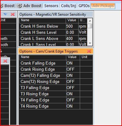
It appears as though you can chose your trigger and home edges to suit? Is this applicable to your ECU, I have set the software to believe it is managing an EMS-4 with a 2jz just for the sake of getting some stuff on the screen.
Cheers,
Jason
3TC Compound Turbo 1976 TA23 - Members Ride Thread HERE
479RWHP on 50psi and 70psi hasn't broken her at the track!
Ok yes NME, this is where I think I might have things wrong, bit confudled, :/
It says it inverts the signal and creates a falling edge significant square wave, and requires a rising edge input, this is the part contrary to the usual arrangement on other ECU's?
I had it set to Rising as I had inverted the input signal to Rising as per the manual, but apon reading it more closely now it inverts that to become a falling, shit now im really fucking confused...
I have the above set to Rising Edge, so am I to understand that it should be set to Falling Edge, IE Falling Edge is what the output of the conditioning ON/OFF circuit should be after the raw signal input of the CAS which needs to be Rising Edge
From the manual...Pg 29-32 http://aemelectronics.com/files/inst...t%20System.pdf
"The internal circuitry on the EMS is different depending on what type of sensor is being used.
Note that there are two different inputs on the EMS for crank and cam position. One for a Hall
Effect type pickup. The other for a VR or “mag” pickup. The EMS-4 crank sensor VR
inputs go through a signal conditioning chip on the circuit board that converts the raw
(zero crossing) signal into a clean 0-5V square wave signal as shown below. (refer pic in manual)
The signal conditioning circuit will invert the significant edges of the raw signal. The
consistent edge of the raw signal in the example below is the rising edge. The conditioning
circuit inverts the signal and creates a falling significant edge.
All VR Crank Sensor inputs to the EMS-4 must be connected such that the rising edge of the
raw sensor signal is the consistent zero crossing edge as shown in the examples above.
Failure to do this could result in misfires or ignition timing inaccuracies.
Verify data with an oscilloscope or contact your sensor manufacturer to verify polarity."
Last edited by dangdang; 04-10-2015 at 10:03 PM.
Just checked my CAL file NME, I have a feeling you have pointed me in the right direction, I've got the cam/crank edge triggers set to rising and they should set to falling as per page 5 here.
http://ftp.aempower.com/cust/EMS-4/E...%20VW%202L.pdf
I'll have a play tomorrow afternoon.
Cheers
Sorted, it was falling edge which was needed, I just had rising stuck in my head as that is what the raw sensor input needs to be
Essentially I failed to realise that the rectification circuit inverts the signal to falling edge square signal.
Wish the documentation was a bit clearer on this.
I think the rising edge MAG option is there in the software for the other higher speced AEM's Infinity etc..
Changed it, locked the timing in back at 10 btdc and it's steady as a rock now right throughout the rev range, no filtering needed, saweet.
Last edited by dangdang; 05-10-2015 at 10:13 PM.
Great to hear mate!
Now on to making killawasps.
Cheers,
Jason
3TC Compound Turbo 1976 TA23 - Members Ride Thread HERE
479RWHP on 50psi and 70psi hasn't broken her at the track!
24+1 4agze CAS with one home reluctor for the dumb fire ignitor removed and the sensor polarity reversed to rising
edge that the ECU requires
Did you need to do this to run the AEM EMS 4 with the CAS? Or did you just need to switch the ECU to falling edge? Thanks in advance
 Posting Permissions


Bookmarks