Page 17 of 19 FirstFirst ... 71516171819 LastLast
Results 241 to 255 of 272

Thread: wiring diagrams and pin outs for people who need them so help them and add more

  1. #241
    C2H5OH Powered Automotive Encyclopaedia George's Avatar
    Join Date
    May 2010
    Location
    Moscow
    Posts
    823

    Default Re: wiring diagrams and pin outs for people who need them so help them and add more

    dumbass, he ain't need that stuff afaik. He will only modify a couple strings in his code to output the proper pulses per km
    USSR GAZ24 with 1UZ-FE VVTi (UCV24) http://www.toymods.org.au/forums/showthread.php?t=60301
    Engine conversion is when you drive a shitbox which costs a whole LEXUS to own

  2. #242
    Junior Member Automotive Encyclopaedia
    Join Date
    Nov 2011
    Location
    qld
    Posts
    1,123

    Default Re: wiring diagrams and pin outs for people who need them so help them and add more

    Cressida needs 32 pulse per revolution of output shaft
    I'm not 100% sure what the a650 has on the output shaft
    But if its like earlier a340 boxes with a 4 pulse it means u need to multiply the 4 pulse by 8 to get to 32
    I've played around with this and had some minor issues when driving slowly and applying brakes
    If he can get 10 or 20 pulse per rev of output shaft then multiplying that by a lower number to get to 32 might work
    But in the end I tell my customers if they want abs to just fit a 32 pulse reluctor on the output shaft or tail shaft

    With 32 pulse count it makes it a hi pulse count per km
    So it depends what signal he has to start with because the higher the multiplication factor he needs to do
    In his controller might cause issues down the track
    Also how does his controller multiply the signal
    Say multiplication factor is 8
    Does it give 8 pulses output instantly for every single pulse input
    This is where I had issues even with a pulse adjusting device way more complicated than the cheap jaycar ones
    But anyway all this stuff is trial and error so he will just have to deal with each issue as it arises

  3. #243
    Toymods member no 341 Domestic Engineer amichie's Avatar
    Join Date
    Dec 2005
    Location
    NSW
    Posts
    649

    Default Re: wiring diagrams and pin outs for people who need them so help them and add more

    The A650E originally had a 12 tooth wheel and a 2 wire reluctor type pick up. The Cressida MX83 ABS sytem has a 32 tooth wheel and a powered 3 wire sensor. For simplicity I made up a new wheel to fit the A650E that has 30 teeth ( I have a 4.3 diff instead of 3.9 so I reduced the number of teeth a little) and I have a circuit that converts it to a square wave pulse ( a simple comparitor circuit). I can easily generate the speedo signal by dividing the ABS signal down in my controller. I just need to know which wires in The MX83 loom are the ABS input and speed sensor input then I can hook up the output of my comparitor etc.

    It's OK if no one has it I will just have to figure it out with the multi-meter tomorrow.

  4. #244
    Junior Member Automotive Encyclopaedia
    Join Date
    Nov 2011
    Location
    qld
    Posts
    1,123

    Default Re: wiring diagrams and pin outs for people who need them so help them and add more

    ok cool so 30 pulses is close enough

    behind glovebox are the 2 chunky grey dash to ecu loom plugs
    the smaller one of the two has a pink with blue a grey with green a violet and a violet with white
    one is 12v ign
    one is ground
    and other is signal to abs ecu
    dont ask me what fourth one is pretty sure it does a loop down to trans wiring then comes back
    this is y i never understand the wiring and diagrams ive seen in the past dont match up
    as the speed sensor has 3 wires but the plug has 4 wires going towards transmission and one doesnt go all the way to speed sensor

  5. #245
    Toymods member no 341 Domestic Engineer amichie's Avatar
    Join Date
    Dec 2005
    Location
    NSW
    Posts
    649

    Default Re: wiring diagrams and pin outs for people who need them so help them and add more

    This is the closet I have found but is still not exactly the same as a series 2 Grande. It covers ABS but my car has a separate 3 pin plug in the engine loom for the speedo sensor.

    http://members.shaw.ca/boltz/7MGTE-M...connectors.pdf

    I've got the Speedo working anyway. Now for the ABS.

  6. #246
    Junior Member Automotive Encyclopaedia
    Join Date
    Nov 2011
    Location
    qld
    Posts
    1,123

    Default Re: wiring diagrams and pin outs for people who need them so help them and add more

    well there is 2 sensors on back of box
    3 wires for abs sensor
    3 wires for speedometer
    later mx83 had elect speedo
    early ones had cable

  7. #247
    Toymods member no 341 Domestic Engineer amichie's Avatar
    Join Date
    Dec 2005
    Location
    NSW
    Posts
    649

    Default Re: wiring diagrams and pin outs for people who need them so help them and add more

    Thing is, the diagram in the link above covers ABS but the Speedo sensor signal wire is in the same plug as the solenoids (6 pin socket). Mine has a separate plug for the speedo ( 3 Pin). I have a spare Grande loom in it has the same plugs as my car so it must be that AUS spec series 2 with ABS are unique. BTW the colours don't match the diagram either. I guess I need to make a summary when complete and post it up here.

  8. #248
    Junior Member Automotive Encyclopaedia
    Join Date
    Nov 2011
    Location
    qld
    Posts
    1,123

    Default Re: wiring diagrams and pin outs for people who need them so help them and add more

    yer like i said the diagrams are differnet to aus spec
    what colour wires do u have all try tell u what they do off top of my head

  9. #249
    Junior Member Automotive Encyclopaedia
    Join Date
    Nov 2011
    Location
    qld
    Posts
    1,123

    Default Re: wiring diagrams and pin outs for people who need them so help them and add more

    well i got of my ass and looked at my diagrams

    speedo sensor wires red/black is 12v ign brown is ground yellow is signal


    abs sensor wires pink/blue is abs speed sensor ground
    grey/green is abs sensor signal wire should have 1 to 3 or 4 v square wave pulse
    violet is 12v power for abs sensor

    violet white comes from abs ecu down to gbox wiring and does not attach to anything on box then does a loop and goes to engine ecu for the secondary speed sensor for the auto section of the engine ecu

  10. #250
    C2H5OH Powered Automotive Encyclopaedia George's Avatar
    Join Date
    May 2010
    Location
    Moscow
    Posts
    823

    Default Re: wiring diagrams and pin outs for people who need them so help them and add more

    back to the basic topic
    guys, check out my collection
    https://docs.google.com/folder/d/0B7...it?usp=sharing

    feel free to share something you have, too
    USSR GAZ24 with 1UZ-FE VVTi (UCV24) http://www.toymods.org.au/forums/showthread.php?t=60301
    Engine conversion is when you drive a shitbox which costs a whole LEXUS to own

  11. #251
    Junior Member Automotive Encyclopaedia
    Join Date
    Nov 2011
    Location
    qld
    Posts
    1,123

    Default Re: wiring diagrams and pin outs for people who need them so help them and add more

    hey george do u know how the security light works on a 1uz vvti
    im pretty sure it goes thru multiplex wires from ecu to dash then to light
    Last edited by dumbass; 21-03-2013 at 07:52 PM.

  12. #252
    C2H5OH Powered Automotive Encyclopaedia George's Avatar
    Join Date
    May 2010
    Location
    Moscow
    Posts
    823

    Default Re: wiring diagrams and pin outs for people who need them so help them and add more

    first of all, there's a number of cars equipped with 1uz vvti from factory
    ucf10 and uzs171 light led+resistor from IMLD pin (positive output)

    another way to know if a key is matched is tc to e1, see if you have code 99 or not

    yet another way is to see antenna output with said led+resistor, or TXCT output with scope or LED. If key is not recognized, led will blink for a few seconds . otherwise it will blink just once
    USSR GAZ24 with 1UZ-FE VVTi (UCV24) http://www.toymods.org.au/forums/showthread.php?t=60301
    Engine conversion is when you drive a shitbox which costs a whole LEXUS to own

  13. #253
    Junior Member Automotive Encyclopaedia
    Join Date
    Nov 2011
    Location
    qld
    Posts
    1,123

    Default Re: wiring diagrams and pin outs for people who need them so help them and add more

    ok ill hook up my scope

  14. #254
    Junior Member Domestic Engineer Karma Supra's Avatar
    Join Date
    Dec 2005
    Location
    Oxfordshire
    Posts
    529

    Default Re: wiring diagrams and pin outs for people who need them so help them and add more

    Hi Guys,

    I'm really struggling looking for some wiring diagrams/pinouts for my VVTi 1UZ -> KZN-185 conversion.

    I have the ECU pin outs for both which covers most of what I need, but am struggling with the equivelant connector on each vehicle, - the main engine -> body plug.


    Plugs on the Hilux that need identifying, the smaller one goes to the diagnostics port, so not so hard, the larger one is the main car/engine plug.


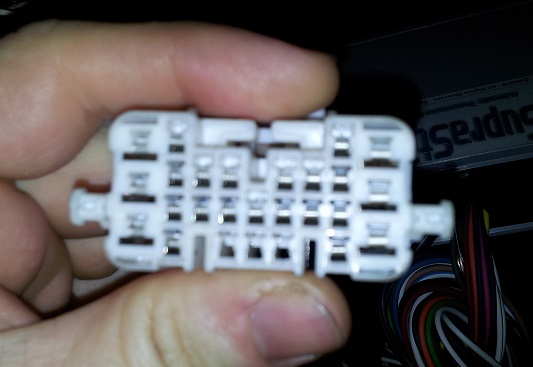
    This is the engine -> car plug on the LS400...
    I have the engine wiring diagrams for both, (can upload of anyone needs) but need the "rest of car" diagrams, - or at least just the pinouts for those plugs!

    Please help!

    Thanks

    Charlie.

    Some kind of BMW
    '97 Hilux Surf SSR-X LTD
    ..::VVTi 1UZ-FE::..

  15. #255
    Junior Member Automotive Encyclopaedia
    Join Date
    Nov 2011
    Location
    qld
    Posts
    1,123

    Default Re: wiring diagrams and pin outs for people who need them so help them and add more

    u will never find diagrams of body plugs unless
    someone has drawn them up themselves and posted
    them up somewhere
    so best thing u can do is get a multimeter and start probing
    most people just concentrate on doing one wire at a time
    find what it does then solder it up then goto next one
    it's time consuming but u eventually get thru it
    even the Japanese workshop manual does not have diagrams
    for that plug

Bookmarks

Posting Permissions

  • You may not post new threads
  • You may not post replies
  • You may not post attachments
  • You may not edit your posts
  •