

 Reply With Quote
3 down... 3 to go....
This type of photo allows me some interesting comparisons....
2 ports opposite each other in view....


never apologize for educating people...Originally Posted by tig321

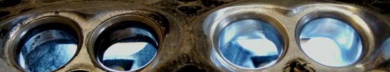
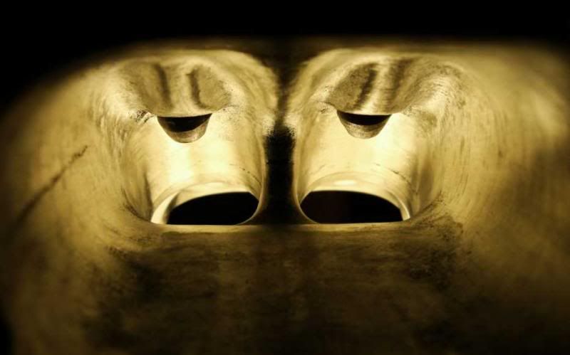
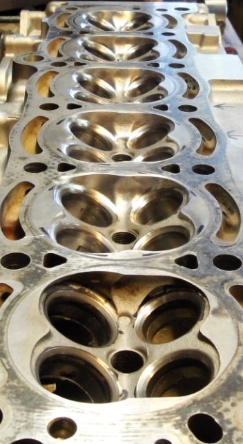
Soooo.... up to now I've shown you #5 exhaust port, and the #5 chamber...
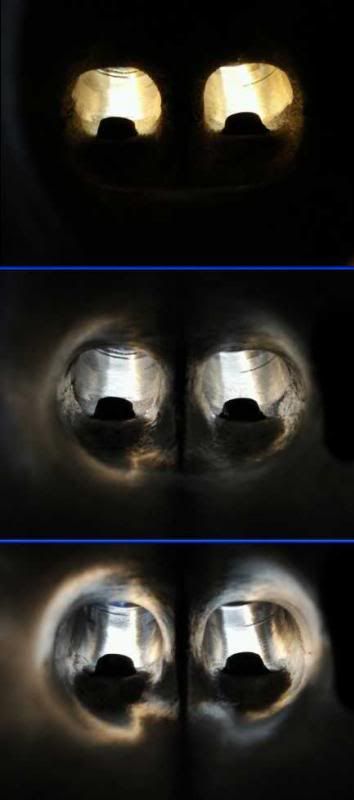
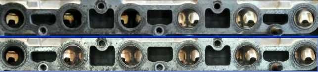
now for a little comparison #5 intake short radius.... and #4 before I work its short radius
Note the port floor is still the port floor (horizontal light line in port center), the short radius, as well as the bowls have been blended.
You can see the ports are directional the port on the right leads away to the right, while the port on the left leads away to the left. Also note the far left bowl, the bowl and port wall are intruding inside the valve radius, note the far right port bowl flows smoothly into the port and out. The very sharp of eye will see the radius change on the inside bowl of #5 where it meets the divider, as compared to #4.
Having looked at your 7M ITB links....
besides the radius.... the very sharp of eye will see the radius change on the inside bowls where the bowls and splitter meet.
Now that I've got the intake side "designed", I proceed on with getting another exhaust in shape... this time #6.
#6 has an "irregularity" in it... the EGR port - hole in far right port.
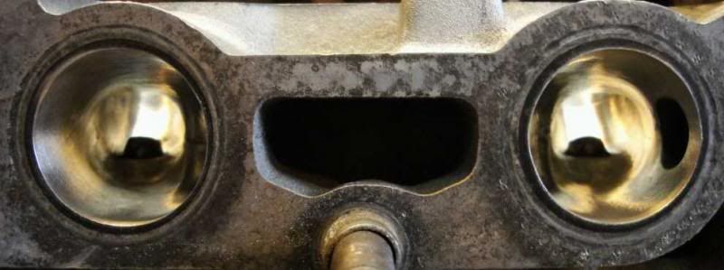
Here is #5 and #6, the splitter for each is just visible in this view, the only light in this shot is shop light
The edge of the EGR port closest to the of port outlet received a mild radius, The other edge was not radiused. I did what I could... considering there is a big hole in the side of the port. I was able to do quite a bit to the bowl and port.
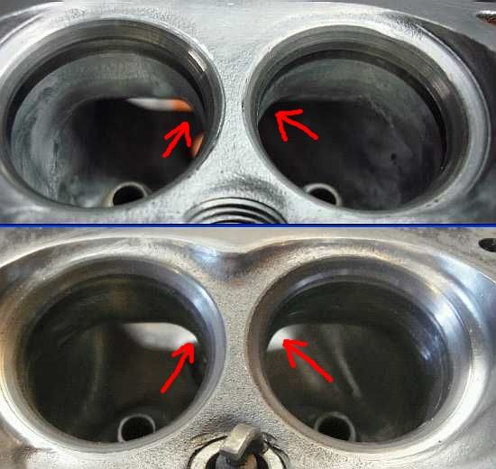
And a 3 panel.... bowls mostly in shape, port transitions from raw to finished* (some hand finishing remained)
The major work is performed between the top and center panel... large sections of the outer walls are removed to allow for a more gradual transition. Those transitions are blended between the center and bottom panel.
More to come.......
Information is POWER... learn the facts!!
3 down... 3 to go....
This type of photo allows me some interesting comparisons....
2 ports opposite each other in view....
Information is POWER... learn the facts!!

Thanks for sharing your work its great to see how this is done.
1989 white supra 7mgte manual
http://www.toymods.org.au/forums/for...pra-turbo.html
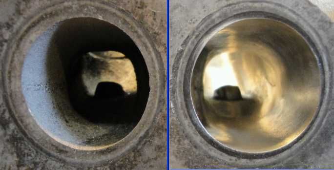
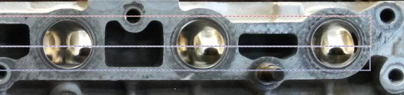
here is my full port view... this is 2 ports... they are similarly directed, but alas... I didn't get a before view of 5 from this angle so I took port 3 as a before
before #3
after #5
You can see the splitter taper, and how it allows for more of the valve to draw on the air fuel mixture. The short radius has a lengthened horizon allowing for more air to follow the short radius to the valve
More to come.... and next time it doesn't look nearly as nice as this post
Information is POWER... learn the facts!!
On my previous post I ended with...
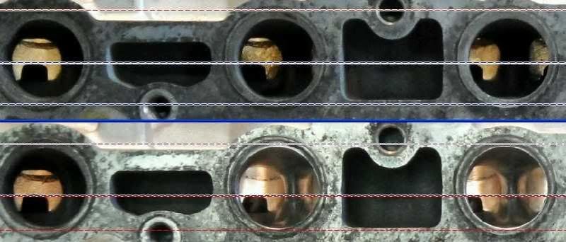
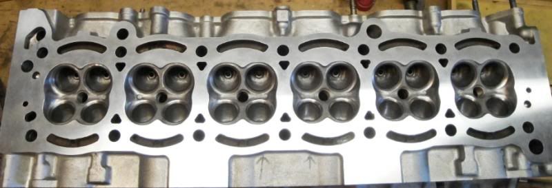
That is because I've encountered a problem. It appears that this head have pretty serious "port drift". My term, it means the port and bowls are not well aligned. In this case the port floor rises incrementally
Ports 4-6
Ports 1-3
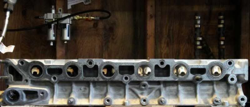
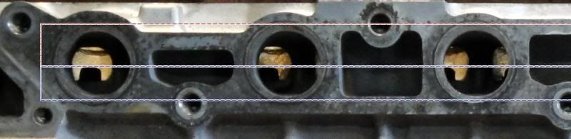
Take a close look at the lines... the 1st line you want to take notice of is the center one, the one showing the valve guides all aligned. Now look at the ports... what do you see? I see the ports "moving" gradually. At first you can't really tell(because I've ported the first 3), unless you look inside the ports. The openings inside in port 5 are not as open as 6, and 4 is not as open as 5.
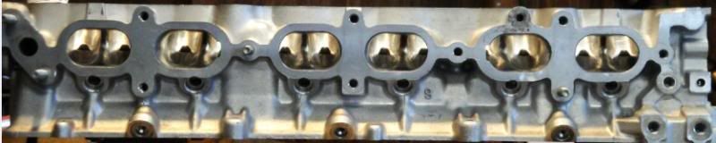
Looking at the 2nd view, ports 1-3 and you can see that all the ports are moving "up" on the head, the available area to port is mostly on the port floors, with only limited porting room available on the port roofs, or in the case of #1, already at the same port height BEFORE porting......
As you can see in this last photo... the mounting surfaces are aligned (top edge), the guides are aligned... and the port roof has no room for me to work, while the floor is making me "hog out" the floor area to get similar results.
Before I begin hogging anything out... I'll be consulting with a few friends... and get their opinions before I proceed further.
more to come..........
Information is POWER... learn the facts!!
It has been a few days now, progress is slow, but there is progress.
I've now got 5 of 6 ports mostly finished
I've reworked exhaust ports 5 through 3 now trying to match the floors, and providing a smooth short radius to allow maximum flow.
and a bit more detail... the dotted lines are not to context... but the views themselves show the changes that have occurred.
I'm holding off temporarily on #1 because I'm hoping the new flowbench insert will be here in time for me to test how bad #1 actually is. Jesse stopped by yesterday and saw, and felt just how bad #1 actually is. For now I think I'll shift to working 4-2 on the intake side for the next bit so I can delay working #1 until I have the new adapter.
More to come.....
Information is POWER... learn the facts!!
Thank you Ian....
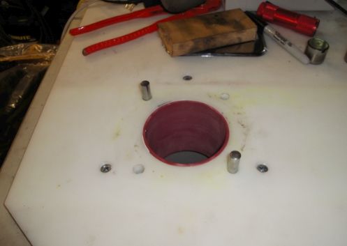
I tried to fit the adapter into my bench top... it didn't slip in so I did some measurements and the O/D was a bit off - bit too large... the ID was a little off as well - a bit too small. Each case easier for me to adjust.
I brought the adapter over to Jesse's shop and put it on his lathe, set the speed for 240 rpm, and used 400 grit sand paper to take it down some.
I got one end to the correct O/D diameter(black lines near bottom), the other end still needs a little bit to pass. the same is true with the ID - one end is 84.01mm, the other is 83.66mm.
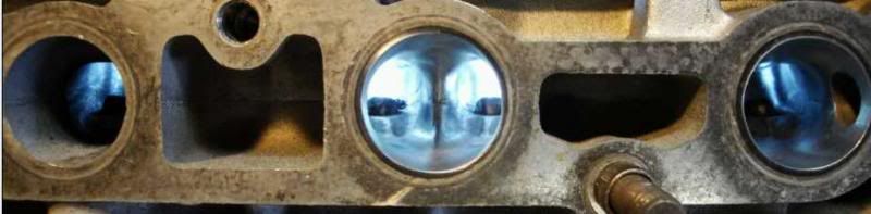
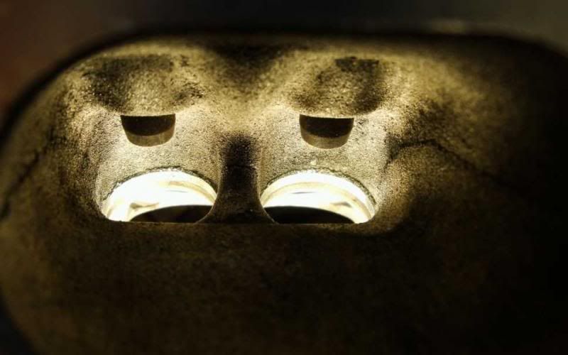
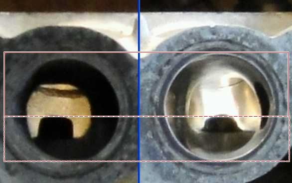
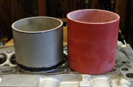
But for purposes of understanding... here are the two adapters...
It doesn't look like much....
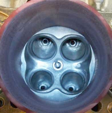
Or does it??
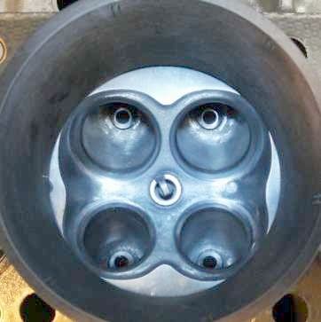
note how now you can see the entire chamber(with red adapter) where with the grey one the valves are all shrouded.
So... I've been saving #1 so I can get another port on the bench, I'll finish getting the adapter to size... re-calibrate the bench to the new adapter... and get the head back on the bench so we can see the progression of the #1 ports.
Thank you Ian... and Jesse......
More to come...
Information is POWER... learn the facts!!
Looking good so far mate!
There is no substitute for PUBIC inches
Never late in an x8
Wow... it has been almost 2 weeks....
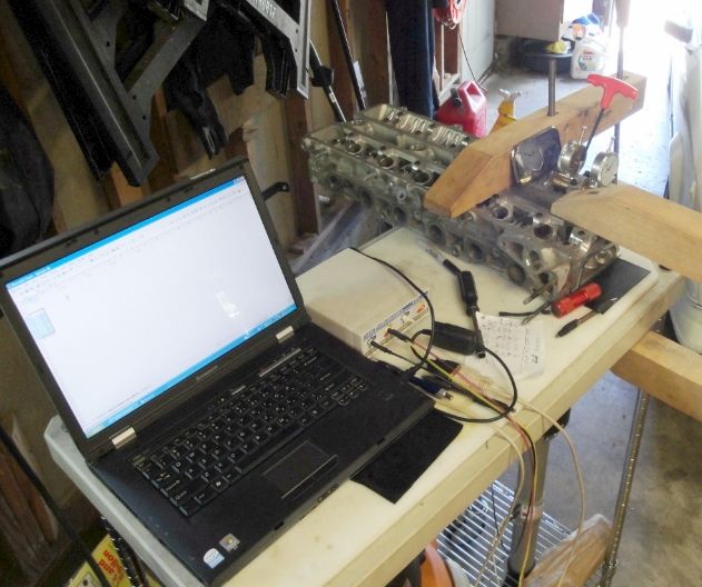
I worked the OD and ID of the new liners with 220, and finally got the adapter fitted to the bench
After fitment, I went about re-calibrating the bench for the new diameter. Once calibrated, I set up the head on the bench so I could measure #1 intake and exhaust ports.
intake - .10" - 82.1, .15" - 117.9, .20" - 150.71, .25" - 175.76, .30" - 188.82
exhaust - .10" - 63.28, .15" - 94.64, .20" - 110.88, .25" - 119.23, .30" - 124.53
Now the first thing that appears different is the intake side already seems to flow above the other ported intakes... but remember we now have a larger cylinder liner for the flowbench. So, if the cylinder liner is now the correct size... why then is #1 exhaust port so poor.
I decided to refit the head on to #5 cylinder to see what the finished ported numbers actually are....
#5 cylinder now with the correct cylinder liner
intake - .10" - 81.95, .15" - 119.87, .20" - 156.38, .25" - 182.65, .30" - 194.8
So with the revised liner the #5 intake port shows improvement over stock beginning at .015" and although not huge, it does gradually open further from there.
Now it is good to note both #1 and #5 had 3 angle valve job so the pre valve job numbers I can't replicate, but based on the earlier tests with the 82mm adapter they are likely to be be lower then after the 3 angle.
It is also worth noting that the short radius on #1 intake port was the best of the 6. In fact overall seat/bowl/port alignment is rather good on #1 intake.
So there is some improvement on the intake side... lets look at the exhaust.
The same(rather good seat/bowl/port alignment) can NOT be said for number 1 exhaust port, flow numbers are actually lower from the start. That isn't good, for we now have the correct liner. I retest #5 exhaust ports and there is a BIG difference...
#5 exhaust - .10" - 63.70, .15" - 95.44, .020" - 118.28, .25" - 131.4, .30" - 139.20
At .30" lift the ported exhaust port(w 3angle) is now flowing more than 10% higher(nearly 15cfm more air flow) then #1 unported port that has had the same 3angle valve job
Number 1 exhaust ports flows poorer then #5 exhaust port did with the wrong liner. Also... my recent references to the exhaust port placement and the port floor crowding the port might have an influence. The #1 exhaust port @ .30" lift with a 3 angle - 124.53 cfm, while #5 exhaust port before the 3 angle as measured with a smaller liner and it flowed nearly 3.5 cfm more... Now that the bench is correctly sized, we'll see how #1 exhaust port improves.
Oh... 5 of 6 chambers are now done as well
More to come....
Information is POWER... learn the facts!!
I'll get this back on the bench once I've finished the intake port and chamber... but I believe all these ports are now capable of 15% greater flow...
I'll get this out to the shop early next week to get the surface machined... but before I do I'll take a few chamber measurements to try and calculate how much the head needs to be surfaced to get the chamber volume back to 39cc... (or smaller - higher compression) if client wants a bit more......
more to come....
Information is POWER... learn the facts!!
.10 - 63.12, .15 - 94.87, .20 - 117.22, .25 - 130.27, .30 - 137.2
#1 exhaust port is now flowing substantially better, and well within an acceptable margin of #5 exhaust port
The "new" chambers had grown to almost 40.2cc, I had the head machined .010" and the chamber volume is again @ 39cc
did you see the "new" hole? It was decided to add an addition coolant passage down outside of #6
I checked the valve springs against specs... they all are short... but barely. The spec is 41.64mm, they all are between 41.61 and 41.5. All of the spring have some tilt, ranging from 1mm to 1.6mm, spec is 1.5mm. I await my clients decision OEM springs for the 7MG are realtively inexpensive @ $5.30 each, 4AG springs are more than double that.
Oh... and I also mentioned the new intake ports...
A bit more to come...
Information is POWER... learn the facts!!
Comp cams 975 springs 'drop in' and will run you around $50/set stateside. They even sell them in boxes of 12...
There is no substitute for PUBIC inches
Never late in an x8
thanks to you all........
I spoke to my client and we are re-using the stock valve springs.... re-assembly will begin in earnest tomorrow... (when it won't be 90+ in my shop) besides regular re-assembly, I'll also be setting valve clearances to the tight side of OEM specs...
Information is POWER... learn the facts!!
The specification: Intake .15mm - .25mm(.006" - .010"), Exhaust .20mm - .30mm(.008" - .012")
My feeler gauges are in SAE... (the FSM does have SAE specs too) What is important to note... there is a little bit of fudge room... since .006" doesn't equal .15mm, it equals .1524mm
Since the specification allows me a range, why not try for the tight side of the range... still in range. Fitting everything tight (within spec) allows me more lift, and more duration from the cam to actually function the valve. Fitting the valves so they have the same, or nearly the same clearances allows for uniform draw on each valve since each valve is open as long, and as high as its twin.
Finally... we only have .300" lift total, why give any of it away if we do not have too.
Check the 5th valve down on the intake side
More numbers... all intake valves are set between .006" and .007", all exhaust valves (except one) are set between .008" and .009". The one except is one exhaust valve is set @ .010, for I didn't have .1083"(2.75mm), so I had to use a .1063(2.70mm) shim instead
using the valve tools to compress valve to allow room to swap shims.
This head is now done....
Last edited by oldeskewltoy; 30-07-2013 at 11:17 AM.
Information is POWER... learn the facts!!
Tight is good :-)
By keeping them all in a close range you also end up with very little valve noise, those numbers you've posted should give a nice quiet head.
To me valve clearances are set correctly when you can check them all with no more than 2 feelers. If done properly, on a stockish healthy motor you should only be able to hear injectors, no valve noise. When i pulled the injectors out of mine and went propane carb, you could hear the coil buzzing over the running of the motor :-)
Good work on this one. I may be bugging you for advice soon as i am about to start building a new, proper head for my propane engine with some mild porting and chamber work to suit the 33.6mm valves. I will do the chambers on my cnc, maybe the bowls too if i can program it.
There is no substitute for PUBIC inches
Never late in an x8
 Posting Permissions


Bookmarks