

 Reply With Quote
very interesting subscribing to see where this goes....


Well... the pressure test went fine.. and the 3 angle is now complete....... apologies for the delays... but this is racing season and Loynings is very busy...Originally Posted by oldeskewltoy

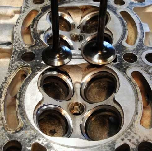
I've not yet had the head surfaced, that will be the last task once all the porting work is accomplished. Below is the head showing its 3 angle, and the valves are showing their back cut... albeit the exhaust valve back cut is barely 1mm in width, while the intake valve shows a much more substantial back cut.
This is #5 chamber... the same chamber I've been doing all the flowbench work on. This chamber will be the exhibit.. after each process I'll be getting #5 back on the flowbench so we can follow the progress.
....... and a bit closer we can see the back cuts, and we can see the 3 angle on the seats...
Before I work the chambers, I'll take a volume measurement and then massage the chambers. All of the machining marks in the chamber will be smoothed, the chamber shrouding around the intake ports will be tapered a bit to improve flow past the valves. I'm not sure how good your eye is... but if you look at the chamber shrouding on the intake valve closest to you... you may see an imperfect arc around the valve... This will be smoothed and blended as well....
The next step is a bit more flowbench time to see if nicely machined seats, along with a 3 angle, AND back cut valves improve flow...... remember no porting as of yet.
More to come.....
Information is POWER... learn the facts!!

very interesting subscribing to see where this goes....
ST177 UZS131 Crown Royal 'G' the pimping limo like daily 1UZFE 144rwkw
DST17T MS53 68 Crown Custom Wagon 7MGTE 266rwkw
It's just about to get good...........
More new numbers........
I'll begin with the exhaust side.... 64.0, 95.2, 115.3, 125.8, 130.8 and posting the earlier numbers.... .10 - 64.10, .15 - 95.97, .20 - 113.73, .25 - 124.32, .30 - 129.58
All are more or less inline with the numbers prior to the 3 angle. The tiny back cut doesn't look like it did anything... the numbers just don't show it..........
Now for more numbers.......
90.9, 130.7, 166.16, 191.52, 205.66...
I don't need to post the previous numbers, but I will below, to know we hit the ball clear out of the park(baseball reference) with this 3 angle and back cut...... I also checked the numbers TWICE and they came up less than 2% different, so I know the newest intake numbers are genuine.....
For comparison......
the old - .10 - 75.73, .15 - 111.48, .20 - 141.57, .25 - 163.67, .30 - 176.37
the new - .10 - 90.90, .15 - 130.70, .20 - 166.16, .25 - 191.52, .30 - 205.66
just... WOW...
A simple backcut, on the back of the 7MG intake valves, along with a 3 angle... really allows far more air flow... So... for those building 7MG engines... get those intake valves back cut!!!!
MORE to come........
Information is POWER... learn the facts!!
I actually have 3 sets of numbers now... and the intake side did improve substantially once it was cleaned....
I checked these numbers twice... could I be mistaken.... yep... I could be... but the fact that the exhaust side didn't improve... and I tested those at the same time I did the current intake readings... for now I'm going to trust that the intake back cut and 3 angle are showing real(genuine gains).Intake:
Before cleaning - .10 - 73.83, .15 - 107.50, .20 - 135.85, .25 - 155.95, .30 - 166.40
After cleaning - .10 - 75.73, .15 - 111.48, .20 - 141.57, .25 - 163.67, .30 - 176.37
I'll know more once I begin porting... (if the numbers remain....)
2 hours later..........
William(original doubter of my numbers)... you KEEP ON QUESTIONING everything that doesn't make sense... because it just didn't make any sense to me either. The exhaust numbers are so there... so how could I have screwed up the intake side so seriously........???
SIMPLE... I didn't change the program to read the intake side. I had changed all the connections, but failed to switch the software from reading exhaust to reading intake....
The CORRECTED numbers........ .10 - 79.42, .15 - 113.57, .20 - 144.88, .25 - 166.91, .30 - 179.37
Intake:
Before cleaning - .10 - 73.83, .15 - 107.50, .20 - 135.85, .25 - 155.95, .30 - 166.40
After cleaning - .10 - 75.73, .15 - 111.48, .20 - 141.57, .25 - 163.67, .30 - 176.37
so now it all seems pretty interesting as the numbers are climbing. At least with the corrected numbers the actual porting should show up with a bit more ease....
Thank you once again. This is new equipment... and the only way I'll get proficient is to use it. I thank you for keeping me honest....
Information is POWER... learn the facts!!
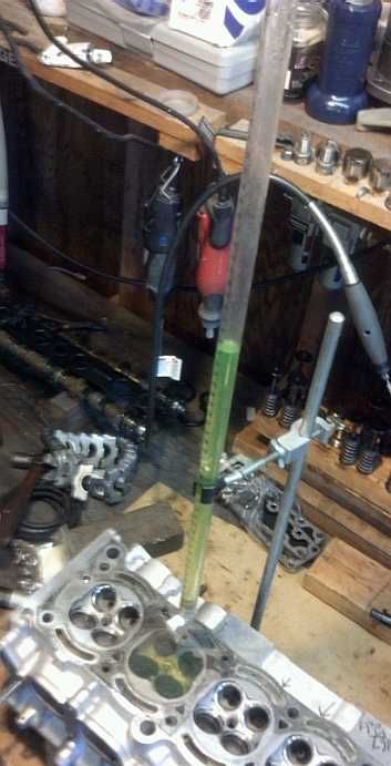
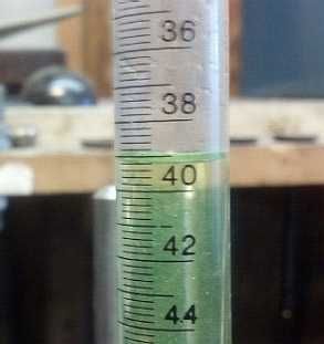
With the head off the bench... but prior to disassembling #5 for porting, I took a measurement of the combustion chamber volume...
I got a volume of 39cc.
Not being as familiar with the 7MG head, as I am with the 4AG head, I do not know if this is standard volume. BUT... we have what we have... I'll do some chamber work, get another measurement and calculate how much the head will need to be machined to retain the 39cc volume
More to come.......
Information is POWER... learn the facts!!
Interesting. Nice writ eup mate. Subscribed.
Yep 39cc is about right for stock chambers. I got mine down to 30cc for uber compression on stock pistons :-)
Any reason you are sticking with standard size valves? Is the motor aspirated or boosted?
There is no substitute for PUBIC inches
Never late in an x8
The client asked me to port it... we are TRYING to do this on a budget(??????) From my exp on a 4AG head, seat removal/replacement with O/S seats costs $800, so on a 7M head I figure it would be $1200... and the cost of O/S valves ( I've read that JZ valves are a decent option too....)
This engine is boosted
How much did you cut the head to drop the volume that much?? I'd like to see photos of your chambers....
Information is POWER... learn the facts!!
There are many things the 4AG and the 7MG share.... unfortunately for this test...... cylinder bore isn't one of them
thank you gentlemen.......
7MG has a bore of 83mm, this one will have an 84mm bore...... my flowbench has an 81mm bore.......
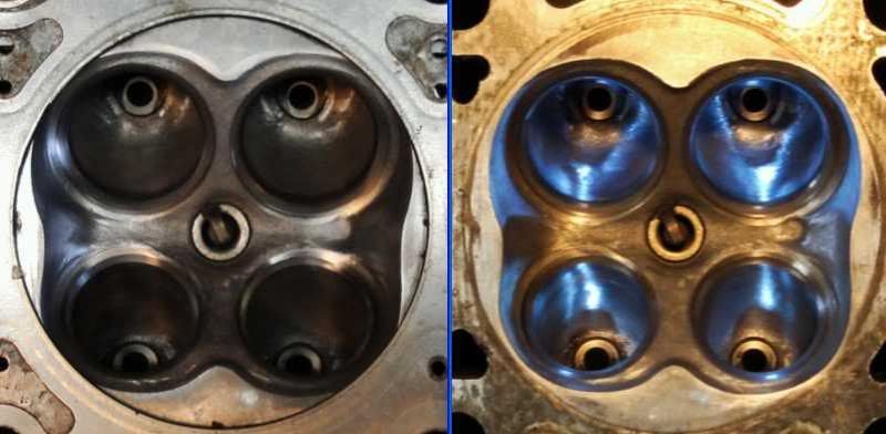
Here... for those who don't understand.... below is a 2 panel...
the right view is the combustion chamber ported out to 83mm, the left view is showing a 4AG gasket centered, overlayed on the 7MG - note how the gasket cuts the corners, how close the gasket is to the outer edges of the valves... now remember the 4AG gasket is 82mm... my bench is another millemeter narrower
There is no way my numbers are accurate.... because well over 10% of the valves are buried behind an 81mm flowbench bore
I still have numbers mind you... but I'll show the pretty pictures first.....
The combustion chamber retains its original configuration, I've tapered all the valve shrouding to allow for improved cylinder filling.
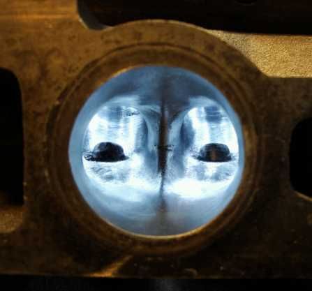
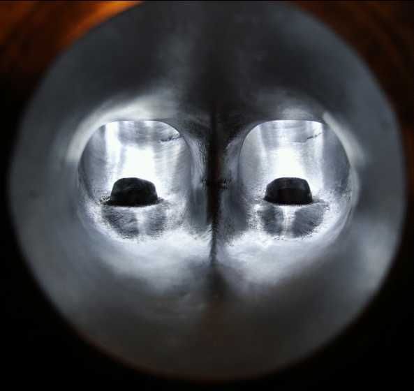
let me introduce to you exhaust port #5....
and a slightly deeper view......
I promised some numbers....
Intake:
Before cleaning.... .10 - 73.83, .15 - 107.50, .20 - 135.85, .25 - 155.95, .30 - 166.40
After cleaning..... .10 - 75.73, .15 - 111.48, .20 - 141.57, .25 - 163.67, .30 - 176.37
After 3 angle..... .10 - 79.42, .15 - 113.57, .20 - 144.88, .25 - 166.91, .30 - 179.37
After porting..... .10 - 79.32, .15 - 115.20, .20 - 146.32, .25 - 170.10, .30 - 182.74
Exhaust:
Before cleaning... .10 - 64.10, .15 - 95.97, .20 - 113.73, .25 - 124.32, .30 - 129.58
After cleaning..... .10 - 64.00, .15 - 95.20, .20 - 115.30, .25 - 125.80, .30 - 130.80
After 3 angle...... .10 - 64.15, .15 - 95.90, .20 - 114.91, .25 - 126.62, .30 - 132.60
After porting...... .10 - 64.20, .15 - 95.35, .20 - 115.84, .25 - 127.70, .30 - 135.60
Now just 5 more to go.......
Information is POWER... learn the facts!!
Sent you a text... in essence... I need a 3" long section of 3.5" OD plastic grey pipe, bored out to an ID of 84mm
Since this is my first 7MG head, and it is going on to a street use 7MGTE... I follow OST rule number 1... do no harm!
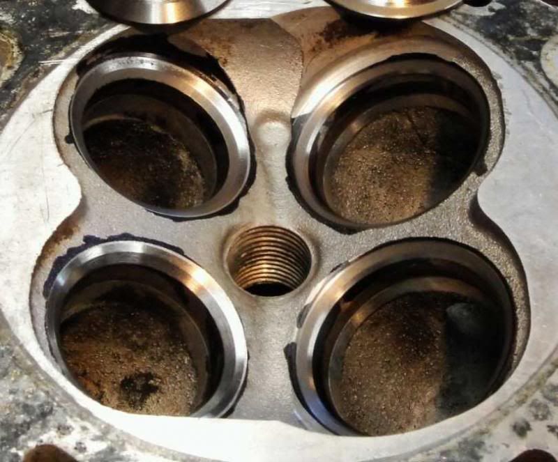
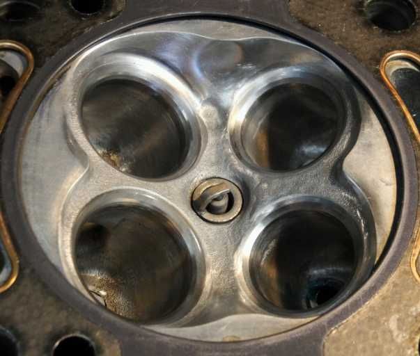
Here is #5 chamber
All of the original machining marks that can lead to pre-ignition have been blended into the chamber walls. The bowls and seats have been blended together as well
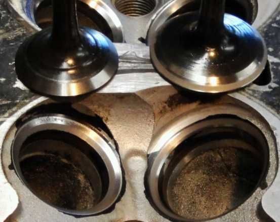
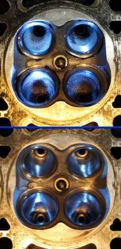
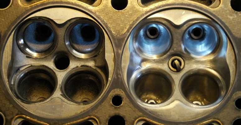
Here is a different view... here I'm show chamber 5 and chamber 6... (both using the same light source)
Here you get a better idea of the chamber work(note no sharp edges), as well as the work performed in the bowls, as well as the gentle taper all the valve shrouding now has...
Note I've pushed the chamber edges, surrounding the valves, to the very edge of the gasket, remember the client is using an 84mm bore, the gasket above is 83mm, this allows me enough room to taper the valve shrouding to improve cylinder filling
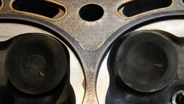
Here is a different view of the chamber work performed.
Both valves are set @ .300" lift, and you can see the exhaust valve shrouding is now about half as much as what it was
More to come......
Information is POWER... learn the facts!!
every time i try to reply to this thread toymods is down again :S
anyhow
that head has had around 0.085" off stock thickness. it was originally cut to 0.080, just above the seats, but it lifted the head so had another light skim while it was apart for studs, which was just enough to nick a couple of seats (note they are not all at the same height!)
photos are from after the 0.085 cut, 30cc measurement was taken after 0.080 cut
no other port or chamber work was done on that head. i just lapped the valves in and stuffed some heavier springs in it.
i call it automatic valve de-shrouding
2j valves are a good bet, and not too expensive. you could fit 34mm, but none available off the shelf. 2j gives you 33.6 and 29 from memory so 1.5mm OS per side. you appear to be using 4age valves in the last pic?
most 7m head gaskets are 85mm but the HKS (i think) have an 86mm bore
There is no substitute for PUBIC inches
Never late in an x8
Those are 4AG intake valves... I'm using them to protect the seats... I don't have any spare 7M valves, so the 4AG intake valves suffice (on both intake and exhaust interestingly enough)
Greddy has 83 and 85, HKS has 86, Cometic has 84 and 86
Information is POWER... learn the facts!!
haha ive got so many 7m valves I used to cut them up for all sorts of odd jobs, great piece of hardened 6mm rod
Head bolt washers are also awesome around the workshop, I have some 4age ones now so got both M10 and M12. I use them all the time for clamping stuff on the CNC, it makes a hell of a racket when you accidentally mill through the hardened steel washers haha
There is no substitute for PUBIC inches
Never late in an x8
I once cut a spare apart when I needed an small boring bar on my hobby lathe. I think I could use it for threading too
Thinking of uses for old valves made me think of something else sixpack did. He used one as a guide on an arbor for a shell reamer to open up the ports
post #8
7M ITBs
I have wondered about the "ZOOLOO" mod as it's known on other forums. It involves drilling holes on the cylinder head.(I'll let the pics explain themselves) Do you know any one who has actually done this? Cleaning up the ''air dams'' as he calls them seems like a good idea also. Those area's look impossible to bleed, and a good place for steam pockets to form.
post #18
7M ITBs
Sorry OST I don't mean to steer your thread off track, just thought it interesting and somewhat on topic.
Hey neat trick, ill have to give that a try
Yep Gordon (sixpack) is a sly old dog, he has done just about everything to these motors :-)
There is no substitute for PUBIC inches
Never late in an x8
 Posting Permissions


Bookmarks