
 Reply With Quote
MSpaint comes with windows, its super simple.


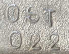
Well... OST-022 represents a few new numbers for me.... The first one is 6.... for 6 cylinders
My client has asked me to do a bit of porting on a 7MG head. It had the "typical" head gasket failure back by #6, so before he re-assembled it, he asked me to see what I can do.......
Now more numbers....
.10 - 62.66, .15 - 92.20, .20 - 111.38, .25 - 123.08, .30 - 127.93
Confused yet?
How about another set of numbers......
.10 - 73.83, .15 - 107.50, .20 - 135.85, .25 - 155.95, .30 166.40
So what do all those numbers mean???
What... no photos? What's an OST head build without photos????? Well... another "new" number... 7 as in Windows 7... as in Windows 7 doesn't support MS Photo Ed anymore
MS Photo Ed was a very simple capable photo editing/cropping program that I've used FOREVER.... for this... I MAY have a solution, but I won't know for a day or two.
MORE to come.......
Information is POWER... learn the facts!!
MSpaint comes with windows, its super simple.
RA23 - Twincharged
JZZ20 - Daily
My old laptop still has windows xp, I just loaded the photo ed on it and do all the editing on it for now. I've downloaded PhotoScape, but to use it, I must learn it....Originally Posted by Kedderz

You are right... kinda... you have the intake and exhaust reversed. Intake numbers are always greater then exhaust.
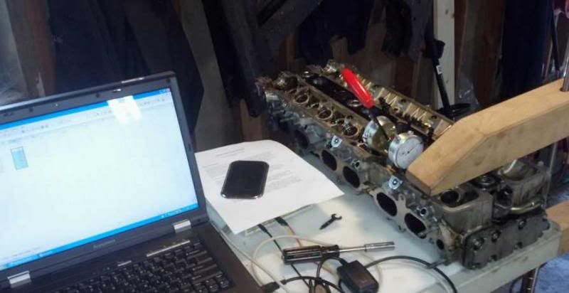
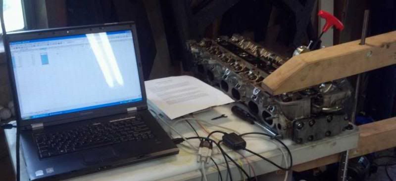
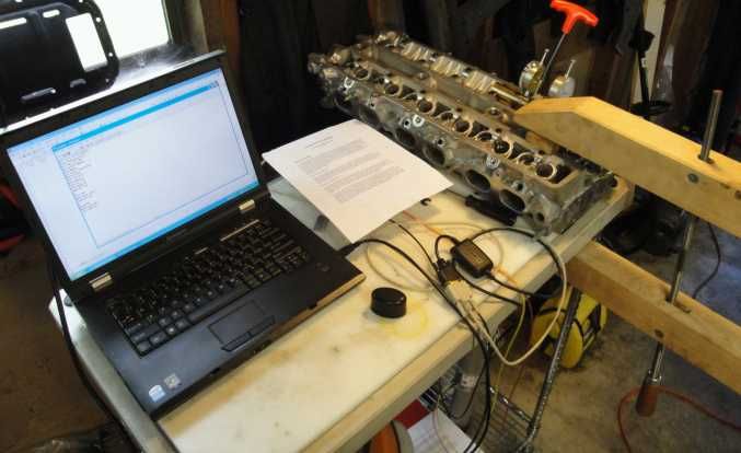
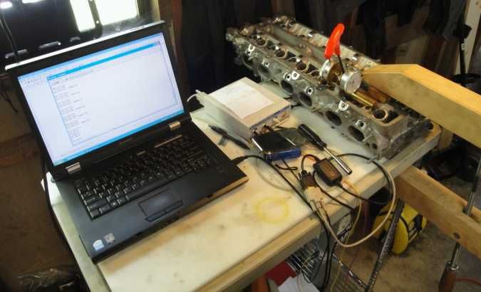
Running a 7MG head on a flow bench. As you see the 4AG valve tool works PERFECTLY... thank you MACK Engineering
photo of the tool - http://i79.photobucket.com/albums/j1...pse5d4d6c9.jpg
checking the intake side...
and the exhaust side...
Btw... if you haven't figured it out yet... I'm NOW offering flowbench services....... @ $40 per hour.
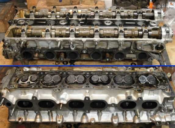
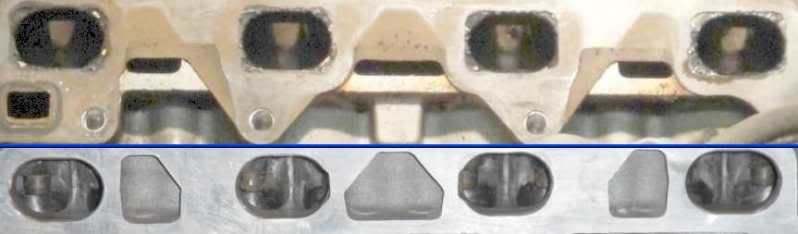
All heads from now on will have one port checked(no extra charge) throughout the entire porting process so the client, and the rest of my readers can SEE the results.
Above is a 2 panel showing the overall head - intake and exhaust, chamber view as well as the top of the head.
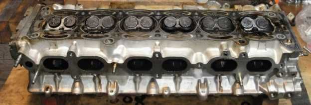
Lets take a more isolated view of the intakes....
Can you see what I see??
What do I see?
Why do I think it is a problem??
More to come
Information is POWER... learn the facts!!
Intake valves are shrouded as hell?
Subscribed to see what you do with this, especially in the chambers :-)
I would STRONGLY suggest having it hardness tested before you put too much work into it. 7m heads go soft as buggery and from there will keep blowing gaskets no matter what. If he is pouring some decent $$ in you would want to start with 90-100rc so it has a few years of hard work left in it.
Also you can see at the back of #6 where they missed a water jacket in the head (wonder why they all blow #6, duh). Easy fix with a small drill bit while you're at it, just go straight down and it will come out in the main water passage.
There is no substitute for PUBIC inches
Never late in an x8
Also hopefully this can be of some assistance for you
http://www.toymods.org.au/forums/tec...s-section.html
There is no substitute for PUBIC inches
Never late in an x8
Thank you!.... I've shared what you said with the owner... do you have a view showing the drilled water passage?
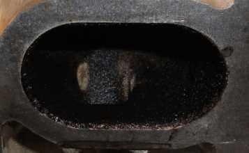
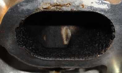
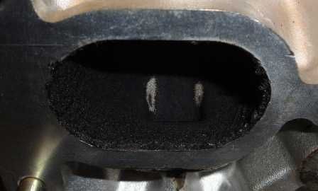
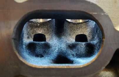
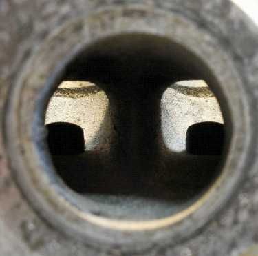
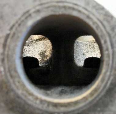
Now as to what I see.... let me show you a bit closer.... here are the 6 intake ports up close
Port #6
Port #5
Port #4
Port #3
Port #2
Port #1
Is it any clearer?? What bothers me about these ports??
More to come....
Information is POWER... learn the facts!!
party pooper.... (j/k)
ok... here is what I see... I see fuel tracks in the port ceiling. This means the injectors/ports are NOT delivering fully atomized fuel. A substantial amount of the fuel is contacting the port roof, and injector port, this is not good for emissions, or power. Ideally the fuel is not dripping from the port roof........
more to come........
Information is POWER... learn the facts!!
Here's one i prepared... well just now :-)
Was quicker than digging through photos lol
Just bung a 5/32 - 13/64 (in your funny speak, 4-5mm in metric) drill straight down til it breaks through. Its quite deep, will surprise you the first time. I had a light shining into the rear water outlet for the photo to show where it comes out.
There is no substitute for PUBIC inches
Never late in an x8
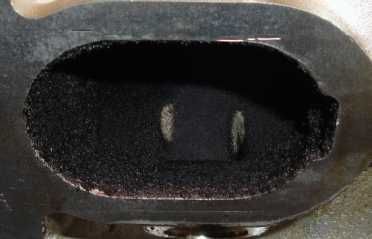
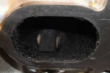
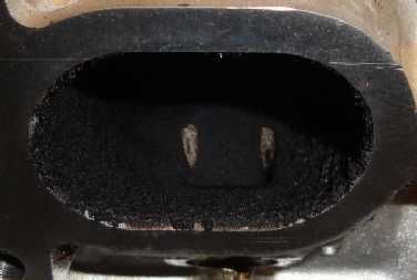
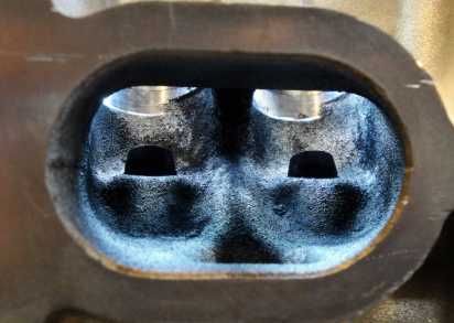
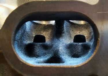
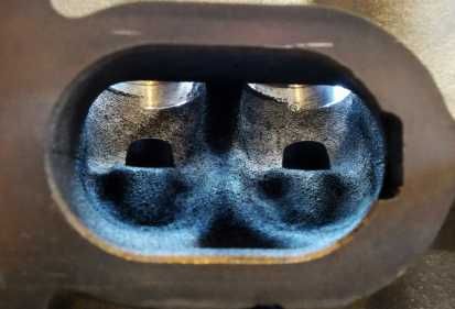
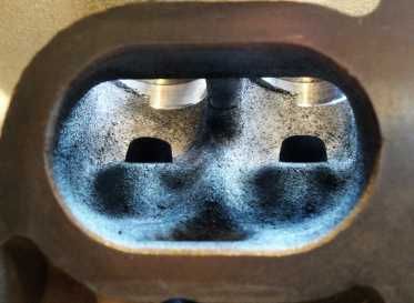
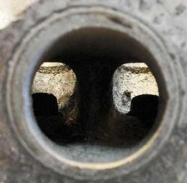
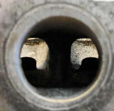
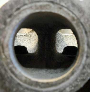
Here are the 6 intake ports... cleaned, and ready........ Oh, for point of fact, the 7MG head groups the intake ports together in 3 groups of 2. Each grouping has a right favored, and left favored port shape.
#1
#2
#3
#4
#5
#6
The first thing I see is the gradual shift the seat bores are at as compared to the bowl placement. Notice how the bores shift and go from a left shift to a right shift on a gradual basis as you proceed from #1 thru #6.
The next thing I see is this amorphous blob at the edge of the injector port. It appears as if it was designed as a port divider, but it acts more like a damn then a divider...
Anyone remember OST-011? Grunts head(4AFE)? It also had an amorphous blob in each port before I tended to them.....
Besides the blob... the guide bosses are poorly shaped, progression from port to bowl is just nasty.......
Tomorrow I'll post up some exhaust port views, and see where we can improve things on the out going side of the cylinder head
More to come.......
Information is POWER... learn the facts!!
high pressure fuel will splash when it hits a surface, and when it splashes off a hot surface, will it further break up droplet size?
"fully atomized" is an interesting termwhat droplet size would one consider to be fully atomised? what droplet size is best for favourable burn speeds?
fully atomised usually means it is a gas (or close to), and has vastly different burn speeds to when there are liquid droplets burning
"I'm a Teaspoon, not a mechanic"
"There is hardly anything in the world that a man can not make a little worse and sell a little cheaper" - John Ruskin (1819 - 1900)
AU$TRALIA... come and stay and PAY and PAY!!! The moral high horse of the world!
I'm usually more careful using absolutes.... ("fully").
As I see it, Toyota's intention was not to spray fuel onto the injector port and the port roof.... IMHO... this is another case of production not quite pulling off what the design (and designer) was meant to do
Information is POWER... learn the facts!!
i had thought there were lots of examples of spraying onto port roof or back of valve, so fuel hits hot surface, bounces off and forms finer fuel mist??
still probably better if you have injectors that don't need that help, and can still achieve flow required
could it just be because those injectors are old and not spraying properly?
"I'm a Teaspoon, not a mechanic"
"There is hardly anything in the world that a man can not make a little worse and sell a little cheaper" - John Ruskin (1819 - 1900)
AU$TRALIA... come and stay and PAY and PAY!!! The moral high horse of the world!
I believe these injectors are suppose to spray at the back of the valves... As to whether or not the injectors are spraying correctly, they will be cleaned and checked, but it seems odd to me that all 6 injectors would have similar spray pattern failures(horizontal in the pintle area as opposed to either vertical... or other angle).
I will recommend to my client that he get the injectors serviced... I also think I may try to provide a bit more room...
Nearly forgot this..........
....... and now for more numbers..........
.10 - 64.10, .15 - 95.97, .20 - 113.73, .25 - 124.32, .30 - 129.58
Exhaust.....
.10 - 75.73, .15 - 111.48, .20 - 141.57, .25 - 163.67, .30 - 176.37
Intakes
Now lets take a look @ the differences.....
Exhaust:
Before cleaning - .10 - 62.66, .15 - 92.20, .20 - 111.38, .25 - 123.08, .30 - 127.93
After cleaning - .10 - 64.10, .15 - 95.97, .20 - 113.73, .25 - 124.32, .30 - 129.58
Intake:
Before cleaning - .10 - 73.83, .15 - 107.50, .20 - 135.85, .25 - 155.95, .30 - 166.40
After cleaning - .10 - 75.73, .15 - 111.48, .20 - 141.57, .25 - 163.67, .30 - 176.37
There is improvement... but remember I have cleaned more then just the ports... I've also cleaned the valves, removing deposits from the back of the valves.
One thing is clear... the exhaust side shows only minimal improvement, almost within a tolearnace factor, while the the intake side... on the other hand.... seems to show substantial improvement.....
Now... for some numbers my client found.....
7M Cylinder Head Flow Numbers
Well... at least my numbers seem to compare similarly to Defiant 7M's....
The head likely has a few out of tolerance valve guides(4 to 6)... I'll know more Monday afternoon...
More to come.......
Information is POWER... learn the facts!!
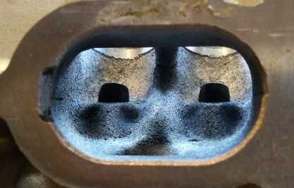
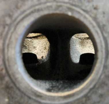
The head is off getting it's 3 angle. Before I let it go, I took a few more pics... this time the exhaust.....
#1
#2
#3
#4
#5
#6
These will get a more gradual taper to them, along with the bowl/seat work, and they will get a bit of work along the splitter.....
More to come......
Information is POWER... learn the facts!!
Actually... I'm still waiting on a pressure test of the head BEFORE the 3 angle. Once the pressure test is verified good, we will commence with the 3 angle.
During dis-assembly I checked for bad guides, either too tight, or too loose. I had thought I had found 3 loose guides (where the valve was too loose in its guide). The suspect valves/guides were all on the exhaust side. I had the guides checked prior to the pressure check and all the guides are usable* - good news for my client as it saves him hundreds of dollars.
* - the worst guides measured out to about .0017" of "play". That is well within the standard of a 4AG valve stem, but is it the same for the 7MG head? Well, having the 7MG engine manual(pdf), they are also well within specifications.
More to come....
Information is POWER... learn the facts!!
 Posting Permissions

Bookmarks