


 Reply With Quote
I think it's actually positive triggered. From what I understand the coil negative produces a positive EMF spike everytime it fires... that's what produces the pulse the IC reads to convert into needle movement.
People have tried hooking 12v tachometer outputs to the tach directly in the past and it didn't work.
I just got a PM from a guy on a different forum who tried the club4ag solution for the by installing a 15k ohm in place of the R4 30k, he said it didn't work all that well. By which I'm 'assuming' at this point the tach responded/worked in some manner, but wasn't accurate or didn't work normally (twitchy/bounced around, worked only part of the time, etc).
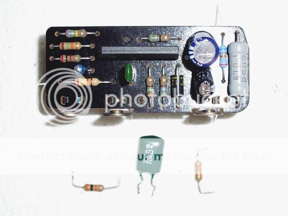
EDIT: Also, part of your diagram looks to be drawn wrong (or my understanding is off). Most likely because of the angle/shadow in the pic.
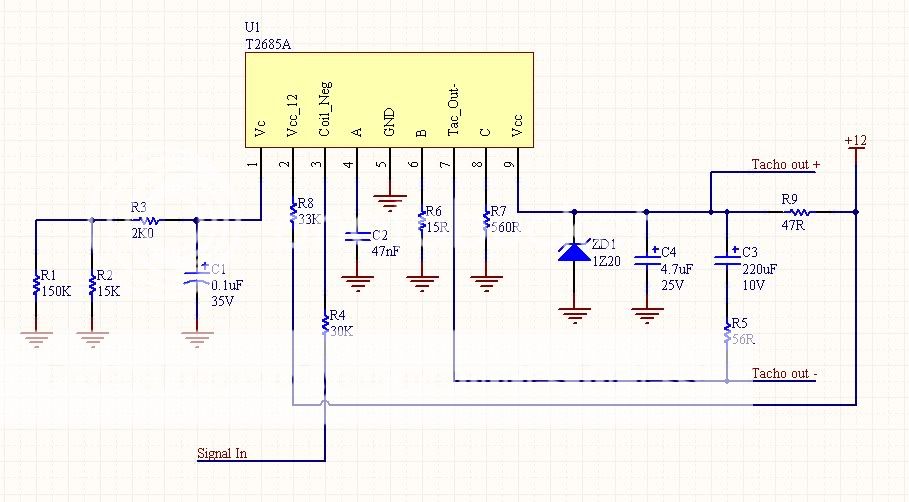
IC pin 7 does:
IC pin 7 -> tacho out (-)
IC pin 7 -> R5 -> C3 -> R9 OR C4 & ZD
IC pin 9 does:
IC pin 9 -> R9 -> 12v (+) in.
R9 is connected to:
IC pin 9 -> R9 -> 12v (+) in.
tacho out (+) -> R9 -> 12v (+) in.
Gnd -> ZD -> R9 -> 12v (+) in.
Gnd -> C4 -> R9 -> 12v (+) in.
Am I making any sense here? Kinda hard since a bunch of things connect in one spot.
Andrew


Bookmarks