
 Reply With Quote
know it's primary coil resistance?
would the flyback voltage be an issue?


Anyone have any sort of idea on what sort of in-rush current something like a Hyundai twin outlet coil would see?
could I switch between coils with a DC solid state relay?
Last edited by Sam_Q; 10-02-2010 at 07:17 AM.
know it's primary coil resistance?
would the flyback voltage be an issue?
"I'm a Teaspoon, not a mechanic"
"There is hardly anything in the world that a man can not make a little worse and sell a little cheaper" - John Ruskin (1819 - 1900)
AU$TRALIA... come and stay and PAY and PAY!!! The moral high horse of the world!
well I guess common sense should of told me to look at the coil resistance but no I don't have it handy. I was thinking more along the lines of peoples personal experiences to get rough idea.
Is flyback voltage some of the voltage spike that comes off the field collapsing?
http://autospeed.com.au/cms/A_110574/article.htmlOriginally Posted by Sam_Q

"Inductive Loads
Theres one other thing to keep in mind when using an electronic relay.
On inductive loads (eg those with coils like solenoids, injectors, motors and horns) a big voltage spike is produced when the power is turned off. To protect the relay, a diode (eg 1N4004) should be wired across the load, band on the diode towards the negative side of the relay output."
"Don't worry what people think, they don't do it very often."
Daily: Glorified Taxi (F6 Typhoon). Out Of Action: Twin-charged Adub. Ongoing Nightmare: Over re-engineered (not) Alfa Romeo 75.
yup.
MS stuff has a flyback suppression circuit you might want to look at, to control the flyback voltage (which can be a few hundred volts).
can switch it with FETs (or whever the right term is.. i'm no elec eng)
"I'm a Teaspoon, not a mechanic"
"There is hardly anything in the world that a man can not make a little worse and sell a little cheaper" - John Ruskin (1819 - 1900)
AU$TRALIA... come and stay and PAY and PAY!!! The moral high horse of the world!
this is the flyback board for when use garden hose sized injectors, but similar idea (i was confusing with ignition for this circuit, sorry)
http://www.megamanual.com/v22manual/minj.htm#fb
from random site
If the Sonata has a Scoupe engine, the resistance should be 0.45 to 0.55 ohms. The required resistance for all other engines is 0.72 to 0.88 ohms.
thats a lot of amps... call it 10-20amp? but at an average of a lot less..
as well as inrush, the disconnect will be like firing coil twice, unless you set the charging window outside the switching time
Last edited by oldcorollas; 05-02-2010 at 09:07 PM.
"I'm a Teaspoon, not a mechanic"
"There is hardly anything in the world that a man can not make a little worse and sell a little cheaper" - John Ruskin (1819 - 1900)
AU$TRALIA... come and stay and PAY and PAY!!! The moral high horse of the world!
whats "MS stuff"?
well I might have a change of plan. I want to experiment on a manually controlled waste spark system. I wanted to control the output of the ignitor but instead think I will go from switching the output of the ignitor to switching the ignition signal from the ECU itself. I guess I would need to need to combine the signals from the ignitor feedback (IGT right?) with diodes to the ECU so it doesn't have a spasm. Anyone see a problem with my idea?
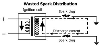
waste-spark coil current requirements would be similar to a single-post coil producing similar spark voltage - only one plug fires into a combustible atmosphere - the other fires into a burnt environment producing a very weak spark with equally limited current draw.
MegaSquirt.
"Don't worry what people think, they don't do it very often."
Daily: Glorified Taxi (F6 Typhoon). Out Of Action: Twin-charged Adub. Ongoing Nightmare: Over re-engineered (not) Alfa Romeo 75.
I would of thought the one that fires in the exhaust stroke would be a stronger spark
nope - most of the energy goes to the ready-to-burn environment.
well how sure are you of that, just because it's ready to burn doesn't mean it's easier to fire the plug. Hence why you can test a spark plug out of an engine and it fires but when it's in an engine because it misfires. The greater the pressure the more voltage and power it needs to jump the gap
contrary to what i thought, the exhaust side sparks first, and this provides a large driving force for the spark on the compression side... and, conveniently, since they are in series, the exhaust side provides a path of lower resistance... so the main resistance is from the compression side.
by definiteion (series) the same "power" will go through both sides of the coil...
can read a bit of detail here too (somewhat complicated as it is talking about ion sensing etc.. which measures the size and shape of the voltage rises or similar..
http://findarticles.com/p/articles/m...1/ai_n9469461/
"I'm a Teaspoon, not a mechanic"
"There is hardly anything in the world that a man can not make a little worse and sell a little cheaper" - John Ruskin (1819 - 1900)
AU$TRALIA... come and stay and PAY and PAY!!! The moral high horse of the world!
if you didn't get a decent spark in the combustible atmosphere, no-one would use it.
As oldcorollas points out - the exhaust side atmosphere has much less resistance so the resulting spark in that environment occurs as the coil begins to discharge and is fairly weak (not at max Voltage required to generate an arc) - that puts a greater potential across the compression side plug for it's own spark event.
well I have to disagree, because of the series thing if one sparks so does the other at the same power level, rules of electricity determine that. I still think that the intake side has a harder time jumping across. This is why a spark plug on the bench even with a huge gap or no electrode at all has a big spark but can need the gap to be closed to not be "blown out" under pressure. Electricity needs about 100V per mm to jump across, and proportionally more under pressure. Of course I could be completely wrong here and I shouldn't be commenting till I read that posted article, just need some more time.
 Posting Permissions

Bookmarks