
 Reply With Quote
I've got a pinout from a 1984 Toyota Cressida dood. (Printed on circuit board) (attachment)
Got this from the toymods repository, which seems to have disappeared.


does anyone have a 5me ecu diagram pinout? bit of a long shot but i cant find one anywhere only 5mge... im down to wiring up the car and i cant let the fun begin without it...

I've got a pinout from a 1984 Toyota Cressida dood. (Printed on circuit board) (attachment)
Got this from the toymods repository, which seems to have disappeared.
1977 RA35 Celica GT - I4 | 2007 GSV40R Aurion - V6
Don't live life being scared of death, live in the fear of not truly living. RP 2012
9 and 13 pin ecu? its a dam good start but i cant read the finer print..
yeah dood. pic attached of loom.
cant help with a clearer pic unfortunately.
1977 RA35 Celica GT - I4 | 2007 GSV40R Aurion - V6
Don't live life being scared of death, live in the fear of not truly living. RP 2012
cheers man... see wat i can make of it...
Open up case.
Read pin outs.
???
Profit.
I have found the below in travels. I'm not sure what the are from, but should help.
That said pretty sure it's also written on the ECU board if you open it up
That first pic is from a MX62 Cressida Haynes manual by the way (I took that picture many moons ago)
Cheers
Wilbo
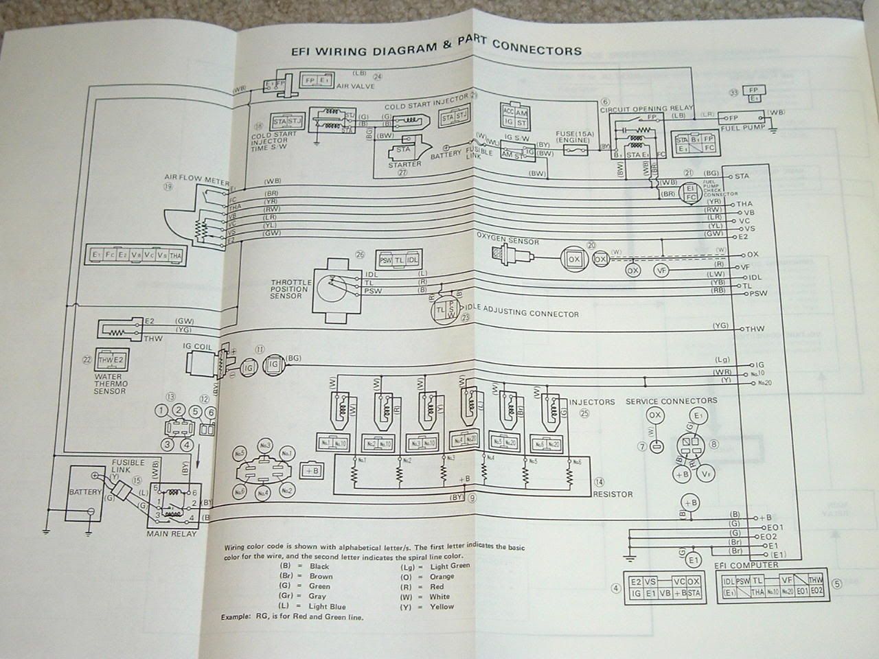
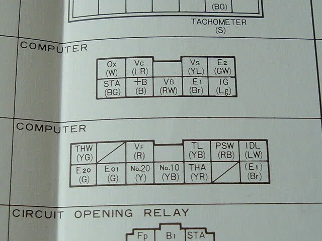
http://conceptual.net.au/~peewee1/wiring/5ME_PINOUT.jpg
http://conceptual.net.au/~peewee1/wi...WIRING_1_1.jpg
http://conceptual.net.au/~peewee1/wi...WIRING_2_1.jpg
http://conceptual.net.au/~peewee1/wi...TAL_PINOUT.jpg
http://conceptual.net.au/~peewee1/wi...BOX_PINOUT.jpg
http://conceptual.net.au/~peewee1/wi...LOW_PINOUT.jpg
Peewee
1985 MZ12 Soarer - 1UZ Powered
2013 86 GTS
Sweet jesus! Love ya work guys!
ok so not being a noob to cars, but a noob to the electric side of things (motor wise) ive mocked up this diagram of the 5m-e ECU + the yellow plug inside the car (part of the body loom?) and im just looki to see if ive got it right and or if im missing anything
cheers in advance

The two green sensors on the ECU plug will remain with the 5ME when you throw it in the bin.
The new engine will come with its own sensors.
Yes, the yellow body plug is the one behind the glovebox that interfaces the engine loom with the body.
THA is only on there because on the 5ME the AFM is part of the body loom and not the engine loom.
What you can do though is connect THA and the AFM FP output (at the AFM) together, and connect THA (at the yellow body plug) to the FC or FP output of the ECU. This gives the new ECU control over the COR (circuit opening relay) as per factory.
Slight variances to this apply depending on what engine is going in.
Also note that the IG input to the ECU comes directly from the ignitor, which comes from one of the plugs nearby. What I'm getting at is when you remove the engine loom from the car you'll no longer have an IG+ source where the new ECU goes.
Peewee
1985 MZ12 Soarer - 1UZ Powered
2013 86 GTS
ok, im a bit of a noob with some of the "slang" AFM(air flow meter) got that one, but "FP" and "FC" i dont understandOriginally Posted by CrUZida

as for the IG+.. what or where am i lookin to plug into?
hate to be a noob but im wanting to make sure i get this right... measure twice cut once is the saying?
Also, found the pinout in regards to the motor (1jz) and if im correct these are the wires i need to be looking at to hook up to the car to make it run? the rest is all part and parcel of the enginge/ecu (doin its own thing)
Wires to hook up : NSW, STA, E01, E02, E11, FPC. M-REL, D1, IG/SW, +B, +B1
FP is fuel pump, FC is fuel controller.
Spend a bit of time reading the diagrams to work out exactly how things work, it will make it easier to wire, and also easier to diagnose when something isn't working properly.
Also read Wilbo's thread on the importance of wiring the M-REL up properly.
http://www.toymods.net//forums/showthread.php?t=54376
Peewee
1985 MZ12 Soarer - 1UZ Powered
2013 86 GTS
cheers crUZida, just knowing where everything goes or where it comes from is a great help, and wilbo's M-REL write up will certainly come in handy i think im just lookin for "what wires" exactly are needed to be wired. obviously all the main power supplies +B, +B1. FPC, D1, IG/SW, M-REL, plus all groundings E01, E02, E11.... but obviously there can only be 10-12 wires that require hooking up in order to start the motor correct? (sensors are not an issue, thats the easy part) with all the above mentioned am i missing any?
 Posting Permissions


Bookmarks