
 Reply With Quote
Subscribing.. Sounds interesting.


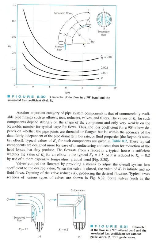
I have been thinking about doing an unsual modification to my 20v intake. Even since I started doing some matchporting on my first spare 20v head years ago I thought it was odd that there was a decent step from where the intake manifold meets the head. Sure I did some matchporting to have a nicer radius but its still roughly a 15 degree bend in the manifold port to the intake port. I have been told anything more than a 7 degree change in direction without a radius will cause flow seperation of the laminar layer causing eddies in region just after the angle change, effectively reducing the cross sectional area and screwing with the harmonics. But I must stress aerodynamics isnt something I understand very well so I could of just said something stupid.
I hate to quote second hand info but I have heard that a worklshop in Vic somewhere did some testing on a flowbench and gained a 10% flow gain by making the inlet path in a straight line. Assuming this is true I still have no idea what this means for real world use.
I have started making an angled spacer to do the same on my engine and I am wondering if its an effert of futility. I will have it so the original manifold bolts up in such a way that I will be able to open a throttle and look down inside to see my three inlet valves. It will be made from one main block of aluminium and smaller block for a clamp (dont ask).
Anyone have any thoughts if there might be a difference in the real world by doing such a change.
Any further questions and theories?
Thanks to Shelldrake for this idea and info.
Subscribing.. Sounds interesting.
Indeed studying fluid dynamics is very useful, I wish I could be of more help with the specifics, but what you've said makes sense to me. What's else would be interesting is how air flow is affected by the sudden change in direction. Generally a tighter radius will sacrifice flow more than a longer radius, so it would be safe to assume a radius of zero would affect it much more (unless there are some interesting effects from the boundary case).
I wouldn't say what you're doing is futile, but you won't know just how well it works without a flow bench, using horsepower or a butt dyno may not measure the difference well enough.
One last thing I'll say was I remember reading somewhere that the intake angle is offset so it better matches the port direction near the valve which would supposedly be an ideal case. That may be complete nonsense though.
"In the beginning, the universe was created. This has made a lot of people angry and has widely been regarded as a bad move." -HHGG

i'd speak with eddie woods from HSD. he would be in the know on this.I hate to quote second hand info but I have heard that a worklshop in Vic somewhere did some testing on a flowbench and gained a 10% flow gain by making the inlet path in a straight line.
ive seen many adds for yager engines, which refer to "wedge plated intake".
itd be a fair guess he's done exactly what you plan.
There are many books I'm sure that show studies of boundary layer disruptions due to direction changes or various bends. The exact angle of 7 degrees or greater would be hard to confirm unless someone has actually tested this for a similar application. Flow around bends however disrupts the boudary layer thickness, and it takes a reasonable length of straight tube past each bend for the boundary layer to re-staibilise (develop).Originally Posted by Sam_Q
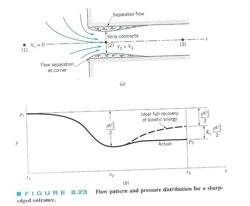
Any sudden changes to a surface's roughness or direction will reduce the thickness of the laminar boundary layer (the layer of fluid closest to the tube wall), and induce turbulence.
The effect and magnitude of this is always velocity dependant, and for slight changes you may/may not notice a difference within the velocity ranges of your rpm.
I would definitely suggest giving it a go. Interested to see if you notice a difference.
AE86 - 3SGTE conversion in the works.
unless there is a good non-performance reason for it to be designed the way it is, wouldn't you assume the design to be optimal considering the amount of money they spend on it?
MX83 2JZ-GTE!!
#YOLO.
some good points here
i also cant comment on the degree of angle to eliminate separation (resulting in eddies and stagnation) as its actually a function of temp, pressure, fluid dens etc etc we use a unitless measurement called a reynolds number to overcome this. there are other unitless measures but are less important
so yeah i reckon its a good idea. but while you may see significant gains for an NA motor i dont think it would be worth the effort for a forced induction motor before reconsidering cooler pipe design etc first
having said that, i have a custom plenum on my motor (1ggte) that was made by RoadRunner it been done really well and does have a low entry angle, it also has bellmouths to each runner, i would look into this also
see below for some inspiration
i think its a good idea
^^^Is that out of a Munson textbook named 'Fluid Mechanics'?
I have that exact one at home!
AE86 - 3SGTE conversion in the works.
yeah.. standard uni text
first up I am suprised on the feedback I am getting on this, thanks to everyone for the info provided.
TurboRA28: if I make some progess I will post it on here, so far I have measured the X+Y co-ordinates of all the holes to within 0.1mm.
Talasas: your right using a "butt-dyno" really isnt that ideal but I would trust that over a flow bench as flow bench numbers going up doesnt mean more power. As for the whole aimed at the valves thing... it sounds like crazy talk.
Grega: does he have a contact number or a website?
Dimitri: well that sounds like the part, again as above do they have any contact details?
Joel-AE86: thanks for the info, as I suspected I had a very oversimplified understanding of how the laminar layer interacts with the walls of a pipe.
PlacentaJuan: good question but i do belive I have a possible answer. I do believe that it would of meant that to make it still fit under the bonnet there would to have to be a decent compramise in the airbox design, have trumpets an even more painfull shape than they already are and possibly have a longer and more difficult to make intake manifold. So basicly: packaging.
SillyCarS: thanks for going to the trouble to post all the info, I will have to wait till I am in a tottaly alert state before I start to process it though.
Ever thought of having that paste-like cutting medium run through it? It would show you where the points of most restriction are, along with helping to reduce them.
Anyway, I'm quite interested in how this turns out. If you're using bellmouths, thought about dyno-testing different length pipes to see how that goes? I've seem some pretty decent gains in certain rev ranges by adding an inch or two to bellmouth length.
The above opinion is just that - my opinion. It is not shared by any business that I am currently or have previously been involved with, nor any of their employee's.
I could do so but it wouldn't help as its not the problem. You see I can get to this just fine with my die grinder but to reduce this angle would mean I would have to take a chunk out of the short turn radius and that would mean the cross sectional area of the port would be unevenly large.
As for the trumper length I am workin on it as I want to shift my power band
sam. no eddie doesn't really "do" websites. he's old school.
Head Stud Development
(03) 9553-2517

im looking for a good set of trumpet set up anyways
 Posting Permissions
Bookmarks