


 Reply With Quote
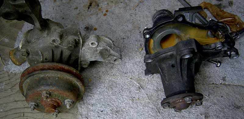
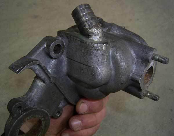
After this is all done the rear half of the housing can be bolted to the 20V front using the steel gasket of the 20V and then bolted to the engine. Seeing the front housing is slightly different it will be slightly off matching the cover of the 20V. While it will still fit it is slightly different but it is very minimal. Here is how mine looked all bolted up:
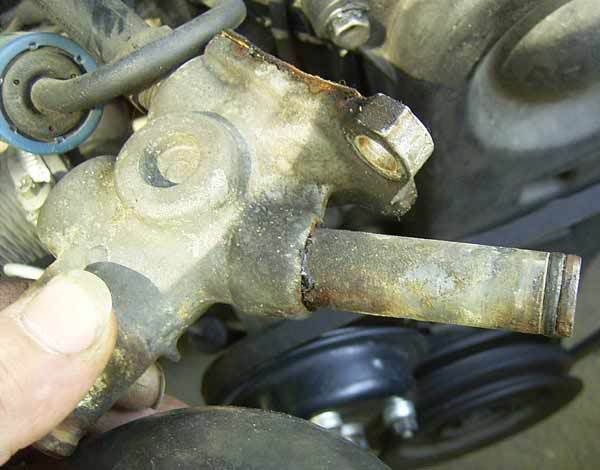
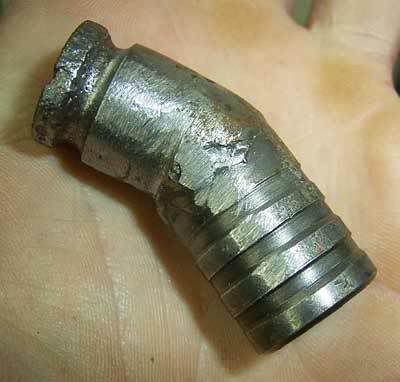
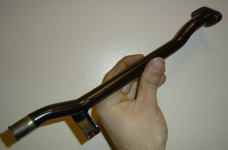
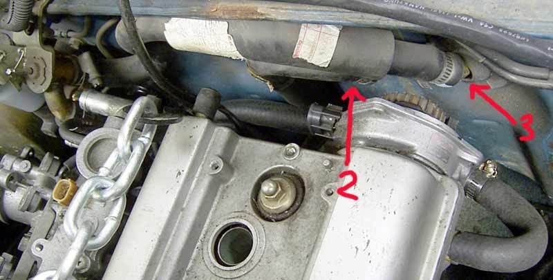
Off the rear of the standard water pump is another pipe that is needed. It normally is bolted to the back and goes under the manifold and to a rubber hose at the end. This isn't a straight swap as it fouls the knock sensor and quite possibly the manifold brace also. The easiest way around this is to just chop it off approximetly 40mm away from the flange. With this cut the rubber hose can still be used for rest of the chopped section, more on this later. I however chose to chop and re weld the pipe on a different angle, I also had to make a new bracket at the end to support the pipe and it worked out well (got lucky!). I ground and painted mine to make it look as close to factory as possible. I was quite happy with how it turned out:
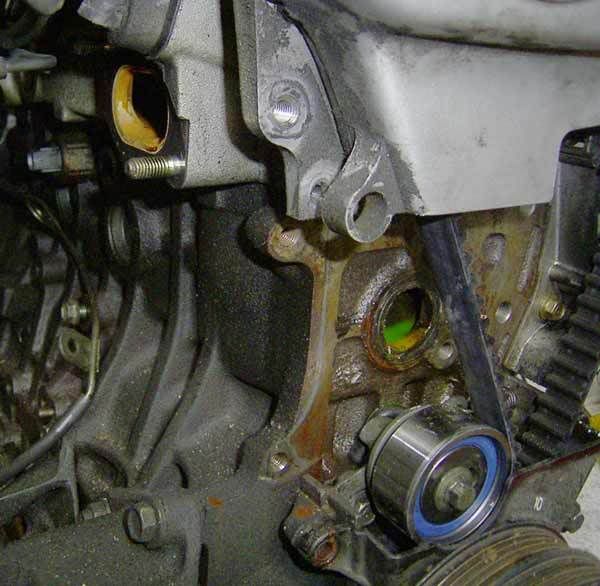
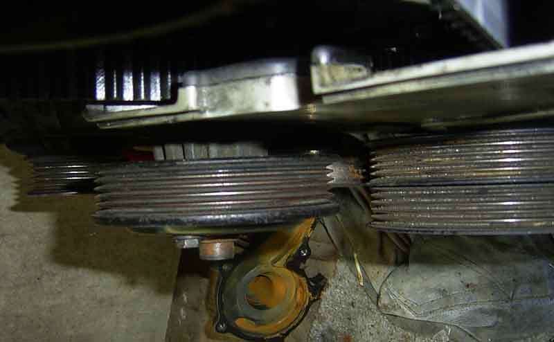
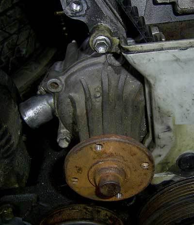
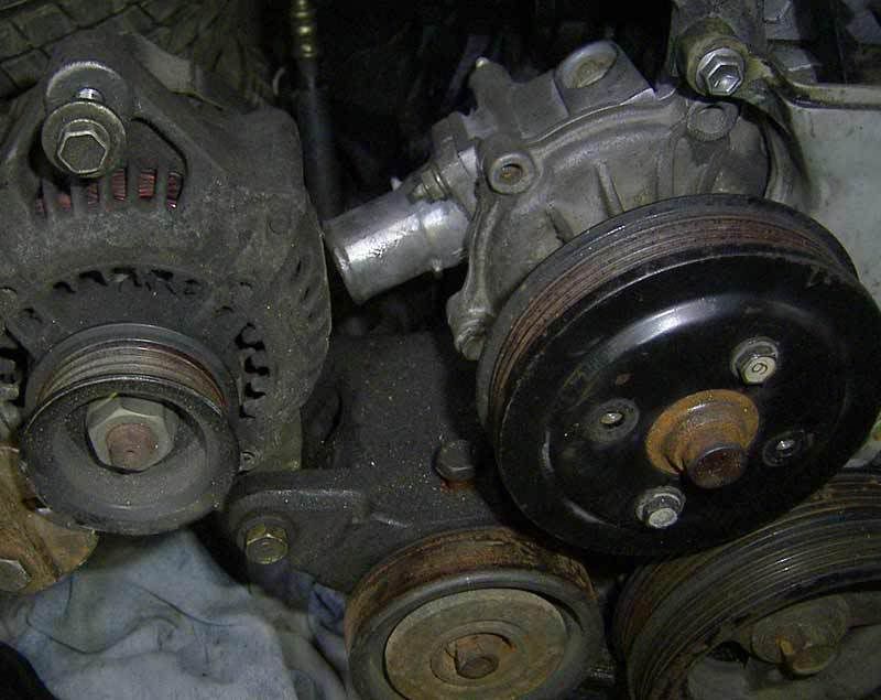
After all this is fitted it brings up the last problem of the new water pump placement; with the new position the top the bottom radiator inlet directly fouls against the alternator as shown in this picture:
By far the easiest way to get around this is to just combine two tensioners and then angle the alternator far enough away that a radiator hose with a sharp 90 degree bend in there can fit onto the outlet. I chose the most difficult option (when don't I?) and made a new custom bracket that holds the alternator low on the other side of the engine. I wouldn't recommend this option at all because it is very difficult to make, difficult to get right, can have some very bad effects if slightly out, etc... It does however place the alternator close to the battery, in a very convenient place. Also of note since I am running no air-con and my custom mount has a traditional tensioner I managed to discard all the original engine tensioners which are heavy, difficult to work with and always seem to seize up. I used a modified Corona tensioner which pivoted off a bracket that bolted to my first extractor bolt. I think for the average person who wants to move the alternator to the other side then what I did is still a bad idea. I would instead say a mount of another 4A based engine such as a 4AFE, etc.. a 4Ac bracket might even fit.
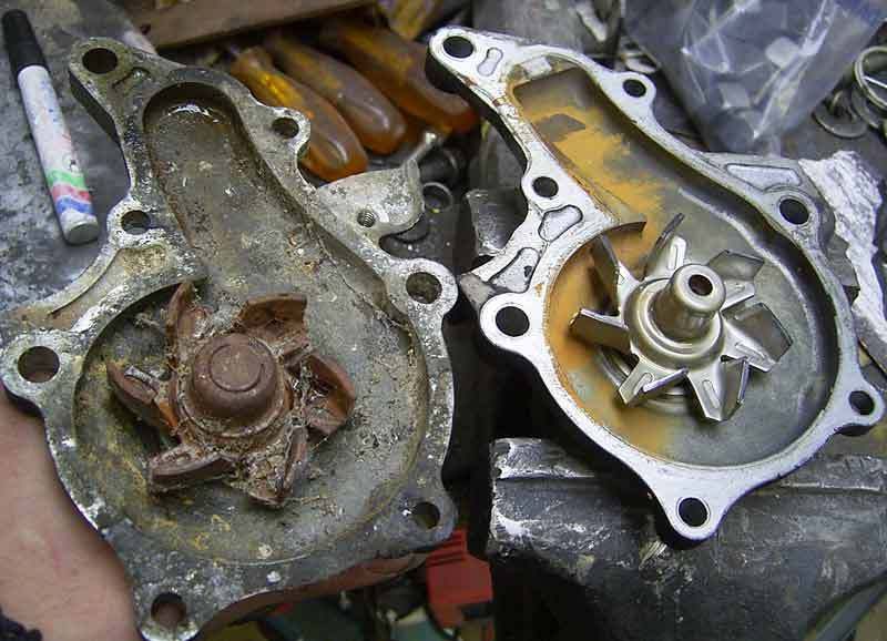
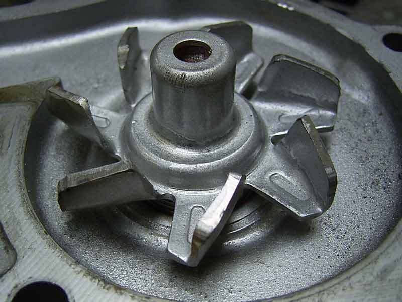
That's it for the water pump, it can now be bolted up and left alone. To fit the pump to the block the original metal gasket from the 20V block can be used..
Custom Top Water Pipe:
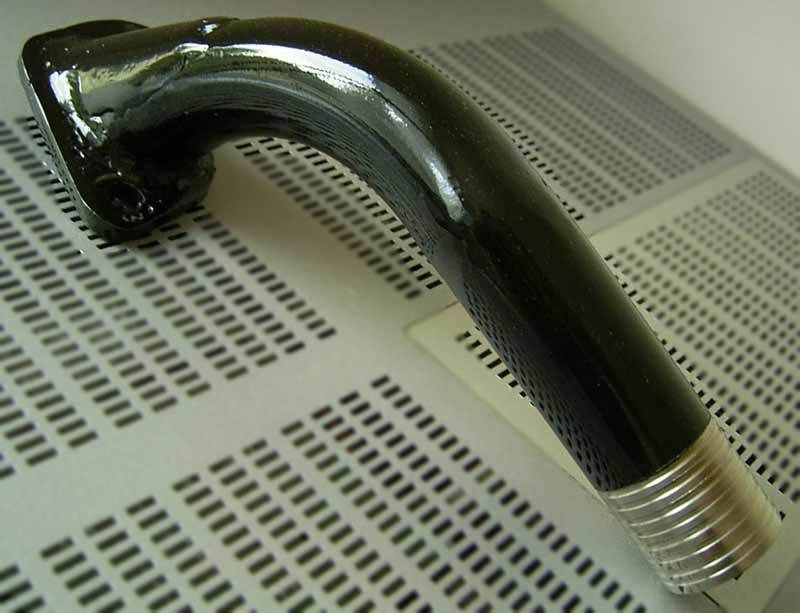
With the new water pump setup in place it leaves the top water inlet of the head exposed. While this previously received water directly from the water pump it needs to be changed to be an water inlet from the radiator. Some people have cut the original fitting and re welded the aluminum to face forwards. While this is a potentially good approach it must be kept in mind that any pipe made that goes first down then up encourages an air-lock in the cooling system is therefore is unrecommended. The easiest option I have seen is to cut it off almost at the flange, weld the very end of the pipe (with the barbed end) onto the flange and then fit a radiator pipe with a sharp 90 degree bend onto it, much like what can be done with the bottom pipe. Another easy way is to cut a flange and just weld a piece of pipe in on an angle, this is very effective and simple enough. I chose the hard option once again and made something that uses all of the opening and is of a smooth and contoured design to maximise flow. I firstly copied the original and made a flange with the oval opening in the middle. From here I welded together a stainless bend to the flange with an additional section to divert the flow through the entire opening, then I welded on a straight stainless section with grooves cut into it for sealing. Initially I though this was all it had to look like and so it looked like this:
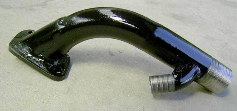
It was at this point however when I found that I had to add the provision for the bypass pipe, So my top pipe ended up looking like this:
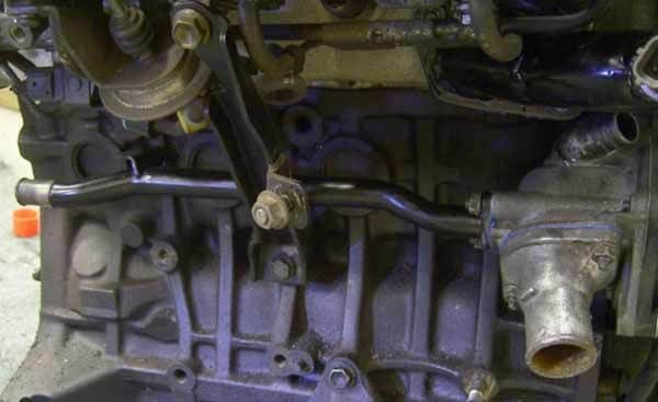
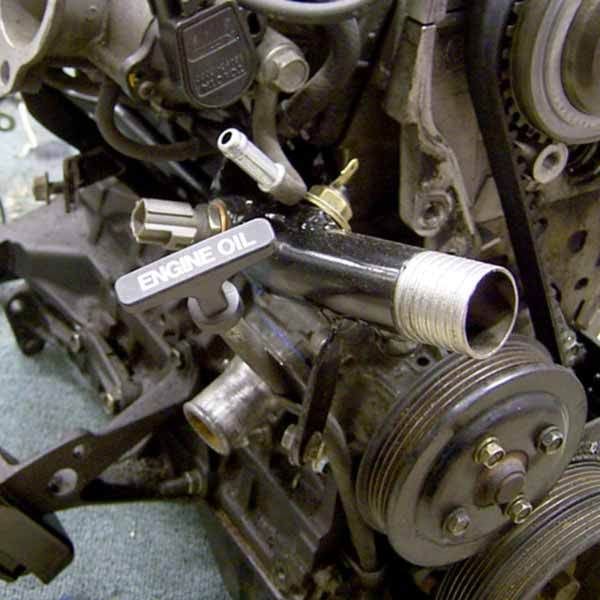
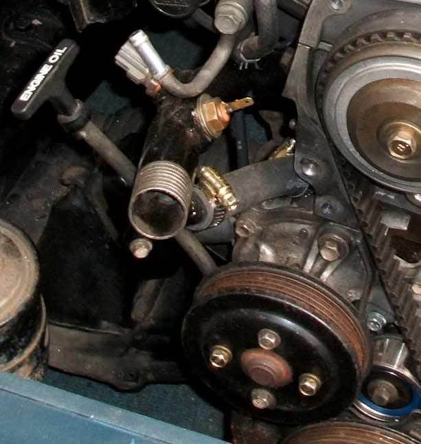
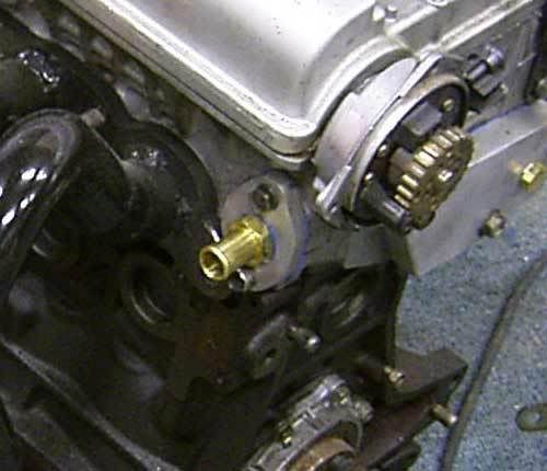
This bypass pipe needs to face the outlet that is glued into the water pump. There needs to be room to fit the rubber pipe and the two hose clamps that are needed. I also decided to add a dip-stick mount and also the engine temp sensors to it (more on these later). Here is mine fitted to the engine without the rubber pipe in place, also in the second picture drawn in place is where the rubber hose is needed to be fitted. I left enough room so that I could bolt everything in place and then fit the rubber hose by bending it and putting it in place later.
The finished setup should end up looking something like this:
Dip-Stick:
As shown by the top picture I made a bracket off the water pump to hold the original 20V dip-stick in place. I have however been told that a 4Ac dipstick can be directly fitted instead. I decided to make the mount to use the original 20V item as it is a much nicer model and also it gives me piece of mind that it's right, even if it is highly unlikely that the 4Ac model has a different length. If a custom mount is made be sure to check that the dip-stick can be taken in and out easily. I initially had some problems with a position I was testing in that the dip-stick would snag against something on insertion because the dip-stick tube was on an angle. Also check that it isn't held too close to the water pump pulley, I moved mine further way that was was necessary because I plan to fit a larger water pump pulley later for an under-drive.
Rear Bypass Plate:
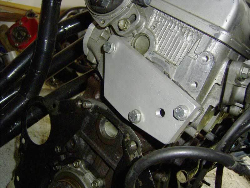
While one other 20V RWD guide suggests drilling a hole in the back of the head I think this is a bit much and risky, it also might cause a limitation in flow and also makes it impossible to use the engine in Front Wheel Drive form ever again. Instead a better way in my personal opinion is to have an external bypass. Firstly unbolt everything off the back of the 20V head and throw it in the bin, it isn't needed. After the head is stripped looking at the back reveals two holes for cooling and three threaded blank holes for mounting.A thick plate needs to be made that can comftabely cover these outlets and be held in place by the three threaded holes. A thickness of about 20mm is ideal and aluminum is highly recommended. I had a threaded hole in the middle of my plate for a temprature sensor, this is the hole in the middle, ignore this as it isn't part of the mounting, heres how it looked:
more below ....


Bookmarks