
 Reply With Quote
i know one has to go to ur inlet manifold after the throttle body.
not sure which one on ur gate though.
got a pic of it or description of the line outlets?
hope that helps.


Hey guys i just installed my turbo with external waste gate.
Im not too sure on how to hook it up to my Electronic Boost contoller.
The wastegate has 2 lines comming out of it. Not sure where these go.
If anyone can draw me a diagram that would be great
Thanks for your help.
i know one has to go to ur inlet manifold after the throttle body.
not sure which one on ur gate though.
got a pic of it or description of the line outlets?
hope that helps.
JZX90 Lovin'

http://images.google.com.au/images?s...-8&sa=N&tab=wi
Check to see if your boost controller has a switch / configuration for external gate as opposed to actuator.
Cheers
Wilbo
Last edited by wilbo666; 31-07-2008 at 10:17 PM.
Wilbo, be careful there.
As my waste gate is setup backwards to that.
The line on the top, is disconnected, whereas the "bottom" line goes to manifold (IE, pressure source)
Cheers for the diagram. The compressor housing does not have any connections on it for the wastegate so do i feed it to the intercooler piping? What is that switch between them?
And what about the other side of the wastegate?
Thanks guys!
You are interpreting the diagram incorrectly, or perhaps it isn't clear enough for youOriginally Posted by Kyosho
The bottom line should go to the "Compressor housing or pressure source" also in the diagram I posted.
If you're not aware of how an external gate works, (simply) there is a diaphragm internally, and when you place pressure on the bottom side of the diaphragm the valve is raised (after enough pressure to overcome the spring is applied).
The wastegate works on the pressure differential across the diaphragm.
If you apply the same pressure to both sides of the diaphragm of course the wastegate will not open, as there will be zero pressure differential and the spring will force the valve closed.
The top port is used as boost control.
It is intended that you supply 'some' boost to the top port (when using a boost controller) to
a) keep the wastegate closed until the desired boost is reached (to reduce boost creep)
b) modulate the pressure differential across the diaphragm so as to effectively control how much the wastegate is open regardless of boost pressure (assuming enough pressure has been generated to overcome the spring force).
Hope this helps
Cheers
Wilbo
A fitting on the intercooler pipe as it exits the turbo is fine.
That switch is a boost controller solenoid, part of an electronic boost controller.
(Sorry I just assumed you were using an electronic boost controller
If you don't have an electronic boost controller, and want to use a bleed valve / ball and spring boost controller then do the following:
1) leave top port venting / disconnected
2) bottom port of external wastegate goes to pressure source with bleed valve / ball and spring boost controller inline.
The bottom line should go to the "Compressor housing or pressure source" also in the diagram I posted. If you're using a bleed valve / ball and spring boost controller as above it should be setup in this hose (And the top port of the wastegate left venting).
Cheers
Wilbo
Good info but to just to clear a few things up,
I do have an EBC, just a black box with 2 hoses controller in cabin (profect B)
Top of the waste gate ---> Boost controller then ---> compressor housing or IC piping (can i fit it to the inlet manifold?
The middle of the wastegate ----> ?
Cheers Wilbo 666
OK...
Step 1, Read the manual for your boost controller.
http://www.greddy.com/img/PHP/products/pdf/682.pdf
Step 2, Read page 11 of the user manual again.
Step 3, Really, have you read page 11 of the user manual?
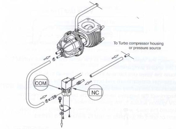
Here is page 11 of the manual, but I've marked where the 'middle' hose goes, hopefully pretty clearly.
Also this comment should make it clear
"Connect the "NC" port to a good pressure source such as the Compressor housing of the turbo using the supplied 6mm Vacuum hose. (It is ok to tap into the same line that is going to the bottom port of the wastegate)"
You can fit it to the inlet manifold if you want, but it will be wrong. It isn't meant to see vaccum, only pressure. After the throttle body there is vac. Again RTFM.
Cheers
Wilbo
Ok i think i got it.
Except im using the original profect B
http://www.greddy.com/img/PHP/products/pdf/687.pdf (pg 4)
With the settings 1 & 4 on
but i think its the same story!?
Cheers
OK,
Yes the manual you linked should apply to you (Page 4).
I think it is quite unconventional to route lines from the inlet manifold however, and I would be using the output of the turbo.
You will want the following DIP switch setting
1 = OFF
2 = ON
3 = ON
4 = OFF
--> External Wastegate
This is the opposite of what you have said ...
Cheers
Wilbo
Haha! All the dip switches i use at work are normally ON at the top. These are different and i just diddnt read them. Woops!
But i think i will route the lines to the output of the turbo, especially before the intercooler.
Cheers for your help wilbo
 Posting Permissions


Bookmarks