
 Reply With Quote
Yes this issue has us tearing our hair out


Hi guys first up, i will just say that i picked a 4TGTE on the weekend and have spent the last couple of days getting it in my TA22.
my issue however is.
The engine is in the car, and cranking...BUT its still not starting. After investigation, we discovered that the ignitors are not pulsing. (there is fuel).
The harness it is connected to had run my 3T with no issues, the only changes to my knowledge are tidying up all the wiring, (no extreme pulling or breakage of wires). so dont think it would be the wiring (but can never tell), but want to explore other options first. So this is the deal......
To OUr knowledge injectors work with a constant 12V and are triggered by the ecu enabling earth and hence completing the circuit, squirting fuel.
however, when the ECU is plugged in and ignition on we have a constant 12V on both 2 pins of each ignitor plug.
When the ECU is unplugged we tested for continuity from the injector plug through the harness to the ECU plug. we found that 1 pin in each plug has continuity with the 12V constant.
AND that each of the trigger wires have continuity with 1 Pin at ALL plugs. meaning that both banks would be triggered at the same time....which makes absaloutly no sense.
This being said - the wiring diagram for the 3T (identical intake system, ECU and overall setup) says that both these banks are meant to be linked, however it also states that both 1,2,4 injectors are linked, while 3 is on it's seperate bank. While at the same time listing injector 1 & 2 on one bank, and 3 & 4 on another. OVERALL, JUST ROOTED I THINK...AND ITS ACCURACY IS QUESTIONABLE.
So, what i am asking for is if anyone has a simple wiring diagram for a 3TGTE injector circuit that works, or correct me if i am way off base, and it is a simple issue.
if anyone has any advice i would be GREATLY appreciative because otherwise i really have no idea, short of making up a complete new harness.
My other thought, could this be the ECU, obviously the ECU, it is the same one that ran the engine before, but there was an incedent connecting up one of the main earths after we just installed the battery where it shorted......but the ECU is fused (did not blow) so i dont think it would have done damage.
Help would be great. cheers all.
Jamie.
Last edited by 79GT; 04-07-2008 at 12:16 PM.
Yes this issue has us tearing our hair out
-------------------------------------
Cheers, Steve
1jz ra28 - AKA - Tyer Fryer
1984 ma61 - stock and slow- ACE condition
So your the one who bought the 4TGTE from Ben at kyp. VERY NICE
Ben wouldn't sell it to me, said it was already sold.
1990 SW20 MR2 turbo Gen III 3S-GTE conversion, 3" exhaust = 264.9rwhp
1985 JZA61 2JZ-GTE + TO4Z = 442.1rwhp @ 18psi
1991 JZA70 Limited 2JZ-GTE vvti GTX30/76r
1994 GZX90 Mark II 1GZ-FE V12
1980 MA45 Undergoing Restoration
Yes accuracy of diagrams floating around is questionable. Your problems are probably not injector wiring but any way a simple way to do it is power to all injectors as you have (based on your test results) and the two earths can be joined and fire in one bank if I can remember correctly.
Basically no spark? = no tacho signal = no injector pulses. You need to get the ignitor firing first. I know this was working good before hand, I would suggest checking your power and earth and coil wiring, and then move onto the dizzy VR sensor signal, check that the tooth is close enough to the sensor with in 1mm or so. Put a screw driver on the sensor pick up that sticks out slightly and check you are getting a spark through the coil output. hope this helps, but basically no spark no injector pulse.
Roger
3j, thanks for that, we are getting spark to the coils, so i wouldnt think that is the issue, unless the ignitor are not passing that signal back to the computer....this would explain, and the coil wires are the only one that we took off, and then put back on...may have got something backwards...will check when i get home tonight.
but what your saying about the injectors is that, 12v on both sides of the plug is correct...??? - and the trigger/earth wires are meant to be all on one bank/circuit....please comfirm.
cheers again though. Jamie
Just confirming your questions.
12v on both sides??? - There should be 12v feed from power source on one side. pinout #10 and #20 feed the other side and earth when the injectors fire, but I can not remember whether they are 12v in normal (not firing state), they may well be I think I can remember measure them both at 12v once but I could be wrong.
and the trigger/earth wires are meant to be all on one bank/circuit....please comfirm??? - Yes #10 and #20 should be wired together if I can remember correctly.
I had the same difficulty with the diagram when I built a loom from scratch so I used a SV11 camry wiring diagram for the injector circuit check the wiring loom thread there should be a diagram in there.
Check you have ig pinout wired correctly to the coil-ve. And only test injector pulsing with an appopriate led test light or a 780- 1kohm resistor and led.
Roger
ok at, this point i asked around and your right.
12volts on both pins - the ecu pulses negative to trigger coils.
the two banks i believe are meant to be linked, also due to the fact that there is only one wire from the ignitor to the ECU. so if it only needs one to recieve it prob only needs one to transmit.
Ive also heard something about the window of the pulses are used to determine which cylinder to trigger or something. (dont really understand that).
Testing the pulses from the dizzy and the ignitor is my next step, (hopefully tonight) and also the continuity of that trigger wire to the ecu (may have a bad solder somewhere).
other than that, i am stumped....could there be a reason for the sudden change in transmitting the pulse from the dizzy or ignitor....We did have to replace the rotor on the dizzy, (we broke the original one)...could this have messed up a sensor if we werent careful in the dizzy.....maybe??? further input would be great.
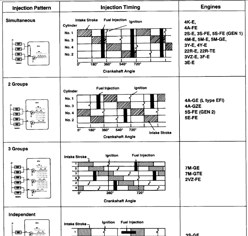
I think you will find that the #10 and #20 injector pins on the ECU are connected internally, and that the reason that two pins on the ECU is used is to provided enough current capacity... (each pin on the ecu is only rated to a certain number of amps, more pins -> more amps OK).
This image might help...you can see all the older style ECU use 'simultaneous' injection!
http://www.autoshop101.com/forms/h22.pdf
Is it possible that the injectors are stuck closed?
Cheers
Wilbo
that is possible..how would i test that though....can I.......
Get an LED with a series resistor (say 2k), or a small (say tiny indicator bulb) and unplug an injector.
Put the led / bulb in the injector plug (if using an led make sure you get it so that the +ve end of the LED goes on the power supply side of the injector).
Try to start and you should see the LED / bulb flash when it is trying to fire the injector/s!
Cheers
Wilbo
ahh cheers mate. that sounds like a plan to me. i will get on to all these things tonight. days nearly over at work thank goodness.
thanks again guys....is it common for these to stay locked shut....also....would it be likely that all 4 of them become locked shut....cheers again.

sorry i cant help you but.......is a 4t a 2L?
* 84 FJ60 - 37's, 308, 80 series coils/diffs and LS1TT in the makin
* 73 KE26 - x4 Brown Wagz
* 73 KE20 NOW 3T-TE
* 84 KE70 Panno
* MX83 LS1 Track Car
IT RUNS. Alright guys, i grabbed an indicator light as wilbo talks about above and discovered that the injectors where getting a pulse. (woohoo). i had a spare fuel rail and ignitors, so i stripped off the original set, replaced the entire rail with my other set which i new worked, and carefully put it all back together. Cranked it over....sputtered and banged a few times...then kavwoooommmmm.
Sooo happy.
only the race bred 4T's were. all the production 4T's came out with only a slightly larger bore than the 3t. which lifted it's cc from 1770 to 1790.
thanks for the help guys. CHAMPIONS.
 Posting Permissions

Bookmarks