
 Reply With Quote
JDM engines do not have an AFM. If your hardware is for US-spec engines (with an AFM) you may be screwed.


I thought I had this sorted with the Profec e-01 manual, a wiring chart and the schematics from the Supra FSM but after I connected the RPM signal wire and the throttle wire I found there was no AFM wire where all the manuals said it should be.
I need to connect the e-01 to the AFM wire on the ECU to apply the boost clamp. So the wire comes from the engine is diverted to the e-01 and then back out to the ECU. This is all done with the optional signal wire from GReddy.
Can someone assist me here to identify the AFM wire? It's not pin 66 on the ECU as this is empty on my 1996 Aristo.
Cheers,
Peter
OMG - Winner of the Official "Forum Comment of the Week"!

JDM engines do not have an AFM. If your hardware is for US-spec engines (with an AFM) you may be screwed.
Norbie!
www.norbie.net
Perhaps the MAP sensor signal on a JDM engine? No guarantees that it works the same with a MAP of AFM though.
|| 91 MX83 Cressida Grande 1JZGTE - Daily || 84 MA61 Supra 2JZGE - Track ||
The box has Japanese on it, and it says "Model MDe-01P, Trust Co. Ltd., Japan" but the wiring diagram for the JZS147 Aristo says "US Spec".Originally Posted by Norbie
Thanks Norbie,
Cheers,
Peter
Last edited by infotechplus; 31-05-2008 at 06:23 PM.
OMG - Winner of the Official "Forum Comment of the Week"!
There is a MAP sensor wire, and the original DIY boost cut module clamped this to a specified voltage. Perhaps I can do likewise with the e-01. Is it safe to try this and see what happens? It's voltage that is clamped anyway, whether it be MAP or AFM.
Thanks Gavatron.
Cheers,
Peter
Last edited by infotechplus; 31-05-2008 at 06:23 PM.
OMG - Winner of the Official "Forum Comment of the Week"!
It would be safe, but you have to be aware, it will do what the clamping the AFM does...
Make the ECU think less air is going in then what really is... So be careful when clamping this voltage and check your AFR
The Profec e-01 reads Air/Fuel Ratio and displays it so I will be able to monitor that.
Cheers,
Peter
OMG - Winner of the Official "Forum Comment of the Week"!
If you still have the factory O2 sensor then measuring the 'AFR' won't tell you much other than rich or lean.
A proper wideband O2 sensor and controller would tell you more!
Cheers
Wilbo
Here you go: http://users.tpg.com.au/adsl0uxv/jzs147.jpg
The Wire you need to intercept to clamp the map signal is labelled "Ar" in that emanage diagram.
I've got everything wired up via a custom harness I made up but now I need to get a signal from the ECU to monitor the airflow. Can I use the THROTTLE sensor for this? There doesn't seem to be any logical place to read airflow. What am I missing?
Cheers,
Peter
OMG - Winner of the Official "Forum Comment of the Week"!
The Map sensor wire would probably be a closer representation of the engine's airflow requirements than the TPS, but in both cases they're the wrong signal. Map doesn't follow the same curve as AFM, so it depends on what the profec will use it for.Possibly the difference can be tuned out, but I don't know anything at all about the profec. You could also build a circuit that uses the map signal and rpm to "construct" an afm signal, or install an AFM.
You're not missing anything - it's not for a map sensored engine, there's nothing more to it.
Mos.
Admin, I.T., Founding Member, Toymods Car Club Inc.
2000 IS200 Sports Luxury 1UZ-FE VVTi, 1991 MX83 Grande 2JZ-GTE (sold)
OK. So I don't have Air Flow so I'll skip that and just measure Throttle, Speed and RPM.
Thanks Mos.
I still have to connect up the Boost Controller.
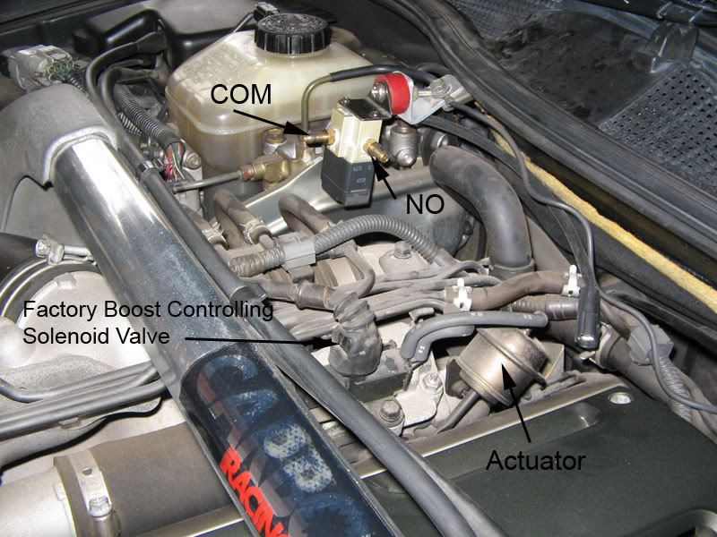
As you can see in this photo I've installed the Profec Valve Unit, and have the two nipples (steady!) in the COM and NO ports as specified in the manual.
Have I identified the factory boost controlling solenoid valve and the actuator correctly?
The instructions say:
"Disconnectthe vacuum hose connecting the compressor housing of the turbo to the actuator at the actuator side and connect it to the "NO" side of the valve unit."
and
"Connect the COM port to the actuator using the supplied vacuum hose"
Can someone tell me where these vacuum hoses connect up?
Appreciate any assistance.
Cheers,
Peter
OMG - Winner of the Official "Forum Comment of the Week"!
No - that's the VSV and actuator for the valve on the compressor side of the second turbo.
The wastegate actuator is on the front turbo, and the VSV is the one that runs to it. It's attached to the compressor housing of the front turbo, right next to the VSV for the second turbo main exhaust valve actuator - it should be the larger of the two solenoids.
I can't tell you exactly which things to connect to what though...
HTH.
Mos.
Admin, I.T., Founding Member, Toymods Car Club Inc.
2000 IS200 Sports Luxury 1UZ-FE VVTi, 1991 MX83 Grande 2JZ-GTE (sold)
OK. Problems solved.
Some hours of web browsing and searching have turned up a couple of references that have identified the correct positioning of the boost controller and associated parts.
Cheers,
Peter
OMG - Winner of the Official "Forum Comment of the Week"!
 Posting Permissions

Bookmarks