


 Reply With Quote
it depends really, on wetaher you are tyring to go for pulse tuning or "inertia" tuning.
having a venturi at the colletor can help a lot in certain designs, i'd suggest reading up on it.
start with this book, its very good


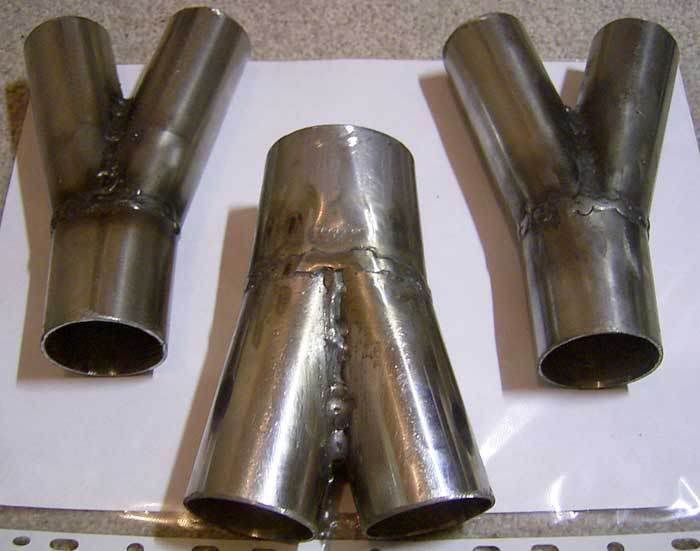
On my previous extractors I made a set of collectors that looked like below for my 20V:
then a little while back I came up with a new design, I made this just today, I failed in my attempt but atleast I tried:
after I came up with my deisn I found this on the burns stainless website:
I want to know has anyone here tried any of these against each other? I want to know whats best for me to make, any theories?
it depends really, on wetaher you are tyring to go for pulse tuning or "inertia" tuning.
having a venturi at the colletor can help a lot in certain designs, i'd suggest reading up on it.
start with this book, its very good
inertia tuning is a myth according to the measurements recorded in "scientific design of intake and exhuast systems. The did recordings and found that a pressure wave has no problem going around the collector and back up another cylender, even with a knife edge like collector like mine.
I wil have a look at that book, thanks for the tip. Do they talk about that collector design?
yes they do talk about collector design, there is a very interesting design for somethign between 4-1 and 4-2-1 headers.
if inertia tuning is a myth, stick a whole lot of right angle bends in your system, and see if you lose any flow potential.
what i mean is sometimes you dont want strong wave tuning, in the interests of a smoother torque curve.
ok I will have a look,
with the inertia tuning I want to clarify what I am talking about to make sure its the same thing as you, and that is that when one exhaust pulse hits a collector it sopposedly pushes the next pulse out of the pipe going next to it. You see bends will restrict the flow and air wont like going around corners in terms of flow but the pressure pulse can. In that book they measure what waveform they were getting at the next branched cylender and they found that they were measuring the wave going around the corner in the collector and back to the head. So even though the exhaust gases were moving though the collector and out the pressure pulse was going around the corner and back to the head for the other cylender. Think of it like this:
if theres a north facing wind and theres a loud sound the sound will travel south as well. So even though the air is moving north theres a pressure wave going south in the form of sound.
Or am I making false judgements here? I admit to being a bit unsure about all this.
The smaller the angle of convergence, the better it is. So in your case, the ones you made first are better.
The gains will also depend on the back-pressure in the Exhaust system due to piping ID.....

Inertia tuning must work, most performance cars are designed around it and they work, the formulas work out. I'd tend to believe that you are misunderstanding the theory.
You mention the wave going up the other side of the collector. If you didn't have any effect in the other pipe, inertia tuning would be impossible. The wave in the other side is the resultant wave created when the primary wave passes the collector.
To the initial question; I'd say that either of your designs would work nicely. You might also want to remember there are other ways of doing it. Most commercial headers have both pipes ending abruptly in a small collector, this will give an enhanced tuning effect over a narrower range than a full collector like you have there. It will have the advantage of a nice anti reversion effect which may be an advantage.
Strange things are afoot at the circle K
I'm NOT an engineer... but the Japan Techno Pro Spirit headers(for RHD....) always seemed the best desing to my untrained eye...Originally Posted by abently

Information is POWER... learn the facts!!
Except for the fact that on the top pipe, the secondary is alligned with the upper primary meaning that the lower primary is different. Then there is the random nasty angle on the lower collector.
Looking at a F1 exhuast, they don't have shallow angles....

Strange things are afoot at the circle K
collector needs to serve as a boundary condition for effective harmonic node function. fine taper/angle f convergence doen not do this. sudden change in volume does (hence venturi style seen above) and also tight convergent angle (i suppose) in f1 above...
Friends
ed_jza80 has not made any friends yet
also, please eject the concpet of back pressure from your head
Friends
ed_jza80 has not made any friends yet
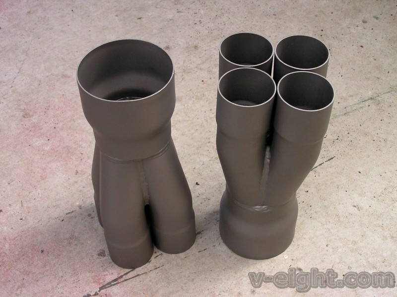
This is what we designed for our headers. It's not made yet, but it's designed for the headers to suit a Mazda 323. There is a 15deg merge with 1.75" inlet and 2.25" outlet, which expands to 2.5" over a distance 1.0" or something. Don't ask me about the physics behind it, I just designed it from plans a mate made...
Oh, and I agree, back pressure is bad, and shouldn't factor in any thought for performance tuning.
Friends
ed_jza80 has not made any friends yet
awesome info guys, so it looks like that even though my second set of collectors was a dud that the concept is still good?
On a bit of a side note how do you weld inbetween the middle of the pipes on a 4-1 collector?
clubagreenie: looks impressive how did you come up with that design?
We bought it...
Friends
ed_jza80 has not made any friends yet
 Posting Permissions


Bookmarks