
 Reply With Quote
Any problem with just using the FC - trigger on the earth side of coil, ign on the other with fused battery across 30 - 87 to fuel pump?
Still gonna cut it out of you crash, thats what im doing


the inertia switches are many on cars in usa
why the fuk would you use a cor when u can use a tacho relay
this thread has gone nowhere cant anyone read
a cor needs a neg signal from the efi ecu to keep it turned on
a tacho relay just needs an rpm signal from the negative side of the coil
doesnt matter if its a 4 or 6 or 8 cyl
doesnt matter if its carby or efi as long as it has a coil or coils
you can even get very sensitive ones that will not affect ignition trigger wires goin to the ignitor
you wont find good ones at wreckers but for 35 to 45 bucks why the fuk would you go to the wreckers and get a 2nd hand one fuking tight asses i say heheheheheeheheheh
Any problem with just using the FC - trigger on the earth side of coil, ign on the other with fused battery across 30 - 87 to fuel pump?
Still gonna cut it out of you crash, thats what im doing
i cant be fuk answering more shit to this
fc is a neg trig on or off
neg coil is a pulse so might not work or your cor will be turning on and off very fast
how long does this stupifd thread have to go
just goto yr lpg shop and buy a tacho relay for fuk sake

every one has there own ideas on this and as with me i appreciate every1s opinions
on my ideas.
I find it more rewarding figuring it out myself with maybe a steer in the right direction.
Dont like the conversation .... then STFU already.
Black Betty >HERE!<
(\__/)
(='.'=) This is Bunny. Copy and paste bunny into your
(")_(") signature to help him gain world domination.

Hi,
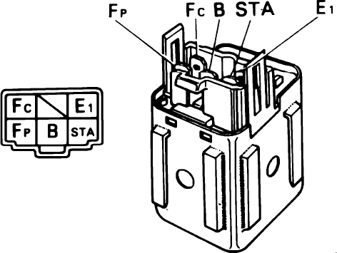
Sorry to bring up an old thread... but I have just been setting up a COR in my brothers AE86 and not having any refferance to go by I looked up your wiring diagram.
I also opened the relay to make sure I was correct and found that it is a bit different to the image posted up.
On the image in the first post, It has the resisted coil as the "starter" to "earth" and the 2nd smaller coil as the "Ignition" to "ECU earth".
The relay I have in front of my has the Resisted coil as the one going to the ECU earth and the smaller coil going to main earth.
Also with the inputs around the other way.
So the one listed as "Starter" is actually Ignition input and has it's earth going to the ECU.
The one listed as "Ignition" is actually the starter input and has it's earth going to the body (Main earth).
The wire colours are as follows.
Input to small coil = Black/White (Starter).
Earth to small coil = White/Black (Chassis earth).
Input to Large coil w/resistor = *Dual input wires* Black/Red (one larger, one smaller wire, Ignition input and refferance to ECU).
Earth to large coil w/resistor = Green/Red (Fc output on ECU, "COR control").
Output from relay = *Dual wires* Blue/Black (one larger, one smaller wire, output to fuel pump and refferance to ECU).
The ECU does not need the refferance wires to work, and you can use these extra wires to run other relays for the other two systems that need to be powered up when using a 4AGE ECU without the 3rd (dash loom) plug.
Eg. The yellow wire on the ECU harness to power the injectors. And the Black/orange (*or Black/red) that powers up the Ignition coil.
Please NOTE: This is from looking at the relay. I have yet to install it and make sure the fail safes work correctly. I may be incorrect with the input wires but I am 100% correct with the earths in refferance to the coils. So if anyone does have any other input on what I have found, please let me know!
I am also aware that relays from different models may infact have different setups/wire colours etc. < So with that in mind this is for an AE86.
They r very easy to hook up
Efi relay turns on with ign the efi power turns power on to ecu and sensors and COR
On the centre pin at the top
So that's power into COR relay normally black red wire
Top right pin is fuel pump power. Normally blue black trace wire
Top left pin is black. Start signal in. Normally black wire
One of the bottom wires is ground. Normally white black trace
Other bottom wires is green red trace. This is the trigger from some Toyota ecus
COR is basically a dual trigger relay
Single power in single power out and twin trigger input
U can use a change over relay to do exactly the same thing
Even with the start signal u just have to wire it correct so u don't get feedback to starter motor
And as long as u use the common input to relay as the output to fuel pump
Hi, Yes... sorry I do know what I'm doing with relays/electrics etc.
I was trying to point out the fact that the image posted in the original post was backwards to what my COR actually was.
Therefore I am not searching for an anwser as to how a relay works, more just a confirmation that I am indeed correct or that I am incorrect and the image is what I should follow.
Going by wire colours alone it seems that I am correct, but the confusion is still present as to why that image shows something different.
I like this image that I found on the internet at one stage
http://wilbo666.pbworks.com/w/page/4...pening%20Relay
Cheers
Wilbo
depends if u r looking into the plug with wires going away from u
or looking into the wires with plug away from u
unfortunately im running low on cors
so i need to order more from the wreckers in japan
I am not looking either way, I am testing the INTERNAL of the relay!
Wilbo666: Nice find mate! The is exactly how I ended up wiring it. Therefore my confusion remains as to why the initial image shown in this thread shows the starter/main earth to be on the "large" coil that contains the resistor.
As there is some discussion in here in regards to wiring a electric pump for carbs, can anyone point out any downsides to using an inertia switch? I have simply run my pump off a ignition fed relay and inline with an interia switch (in case the worst should ever happen).
This should cover the accident angle and I understand that I cant have the car running on IGN without the pump running even if the engine is not, but I can live with that.
Devils - Good point. I never considered the resistor in parallel to the coil when making the initial images. So it could well be that the two coils are reversed. However having a look at the images again I can't see how else they could be connected since IG+ must be connected to the switched feed to the fuel pump. Possibly there have been different versions/types of COR... or I just found a wierd picture when drawing those diagrams
Hen
I need a working 4AGE bottom end. Pref smallport GZE, but all others considered. Also complete motors.
Drift Volvo. Was fun. 2JZ next time.
Devils, I have one of the following COR'sOriginally Posted by Devils

Part number 85910-12080, COR has 5 pins, but connector has 2 wires coming out of Red Black and 2 wires coming out of Blue Black?
Is this the type of COR you are referring to in above post?
Are you saying that wires are reversed for STA and Earth?
Usually I would wire like so
White/Black - Wires to to STA - Starter/ECU Start Signal. - CHANGE THIS EARTH?
Black - Wires to body earth - Wire to closest earth point. - CHANGE THIS STA?
White/Red - Wires to EFI Relay - +12v Ignition Switched power (Run through a suitably sized fuse, 10A is usually fine, but depends on your fuel pump).
Green - Wires to engine run signal - "FC" pin on 4AGE ECU. Or if you are running an AFM engine, this wire should connect to the AFM.
Blue/Black - Wire to fuel pump positive - Gives power to your fuel pump.
I should add, Its on a 1UZ so I don't need reference to ECU
Can't edit posts?
I have been looking at Circuit Opening Relay Wiring - Rollaclub for pin out diagram.
I think this reference might be wrong.
 Posting Permissions


Bookmarks