Page 1 of 2 12 LastLast
Results 1 to 15 of 24

Thread: DIY inexpensive engine management

  1. #1
    Forum Member 1st year Apprentice
    Join Date
    Feb 2009
    Location
    MN
    Posts
    23

    Default DIY inexpensive engine management

    I posted this over on the mr2 boards, but I thought it might be useful for folks here as well.

    This details the installation of a chipped Honda ECU on a gen2 3SGTE engine in a 1991 MR2 turbo. I've been running this setup for 3 years now, and the total cost for essentially standalone engine management was under $300US.

    WIRING

    ECU

    ECU pinouts for Gen2, Gen2b, Gen3 and ST165 3SGTE to Honda/PGMFI can be found here:

    http://www.apexology.com/files/schem...E_to_PGMFI.xls

    The ECU plugs are read like this:


    The MR2's 3SGTE and most OBD1 (92-95) Hondas use the same ECU connector.

    If you don't have a connector to make a jumper harness, you can wire it this way:

    Not for the faint of heart, but it's not particularly difficult once the PC board connector is taken off and can be moved around easily. There are several soldered screws on the underside of the board- heat them with a soldering iron, then use a screwdriver to remove them with the iron still touching them. Cut the connector pins about halfway down and start jumping wires.

    Alternately, http://www.onlinecomponents.com/buy/AMP-TYCO/174518-7/ usually stocks the female (ECU) side plug. As of writing this, they have 264 pieces in stock and want $9.22each. They have a minimum order of $30 (or did when I bought them). I posted this years ago, I have no idea why it was never stickied.

    The male plugs are part #'s 174514-6 (16 pin), 174515-6 (22 pin), and 174516-6 (26 pin), with contacts being part #'s 173631 (large) and 173716 (small). You'll need 16 of the larger and 48 of the smaller ones. Honestly, it's easier to just go to a junkyard and hack the harness out of an Accord. No one takes the ECUs from those because they're not as well-hacked, so the harnesses/plugs are usually still there. It's under a metal cover beneath the passenger side footwell carpet. Takes 10 minutes, tops.


    DISTRIBUTOR

    This part assumes you're going to do this the old-fashioned way- install a Honda distributor onto the 3SGTE head. I'll cover the mechanicals of that later on.

    The preferred method of wiring the distributor is to use the internal ignition coil and Honda ignition module. Stock Honda ignition components have been tested to over 500whp, so this qualifies as an ignition upgrade as well.

    The wiring is like this:


    I recently realized that the gen2 and gen3 3SGTE uses different colors for the distributor wires. On those engines, Ne is yellow, G1 is red, G2 is green and G- is black.

    - CKP-M, CYP-M and TDC-M can all be joined right at the distributor, since they're all referenced to ground as soon as they enter the ECU case anyway. This allows the use of the single G- shielded wire to carry the ground reference. My car is wired this way with no ill effects.

    - Combining the ground wiring frees up a couple of spots in the Honda/Sumitomo distributor connector as well (8 positions), allowing all the necessary wiring to go through a single connector.

    - I know that at least on the earlier MR2s (~91-92) the pins can be removed from the original distributor connector and slotted directly into the Sumitomo plug housingn with some minor trimming on the back side of the housing. The seal grommets on the wires are larger on the MR2 side, but the pins are identical. Less cutting/soldering is always better.

    IAT sensor

    The most common place to install the IAT sensor is in the space where the (now unnecessary) cold start injector used to be. I used a Honda IAT sensor, but the truth is as long as you know the resistance scale, any deviations can be compensated for in the software.

    Here's a sensor from an Audi 1.8t AEB engine (99 A4, etc):


    and it's corresponding resistance scale:


    Note that this sensor uses the same connector type as the cold start injector on the 3SGTE. All that is necessary is to connect the (not green) wire of the harness to ground.
    Last edited by grue0038; 12-04-2010 at 05:04 AM.

  2. #2
    Forum Member 1st year Apprentice
    Join Date
    Feb 2009
    Location
    MN
    Posts
    23

    Default Re: DIY inexpensive engine management

    CHIPPING/MODIFYING THE HONDA ECU
    This information is all borrowed from the PGMFI wiki, since they can 'splain it better than I can. The ECUs we're talking about here are the P06 (92-95 Civic EX, DX, CX), P28 (civic Si), P72 (92-95 Integra GSR) and P74/75 (92-95 Integra non-VTEC). There are a few others that work, but these are the most common.

    You can do this yourself if you're handy with a soldering iron, or there are plenty of people out there who will perform these services for you for a price.

    Honda was nice enough to tell us how to do it:


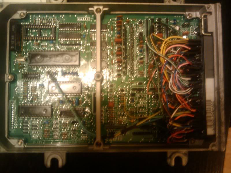
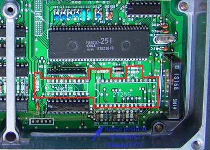
    We're basically just populating the portion of the board within the white dashes with the components listed. Desolder the holes (RadioShack sells a desoldering iron that works very well for <$15:
    )

    28 pin EPROM (www.moates.net carries chipping kits for ~$15-20)
    74HC373 octal latch.
    C51 and C52 are 0.1uF capacitors
    R54 is present on some boards, not present on others. It is 1k ohms.
    J1 is a wire jumper to tell the MCU to use the external ROM.

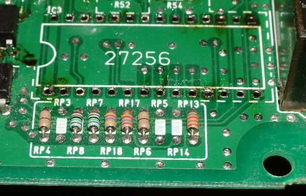
    If you happen to have an ECU from an automatic, you can convert it to manual by removing RP17 and RP18, and soldering in a jumper where RP18 used to be:


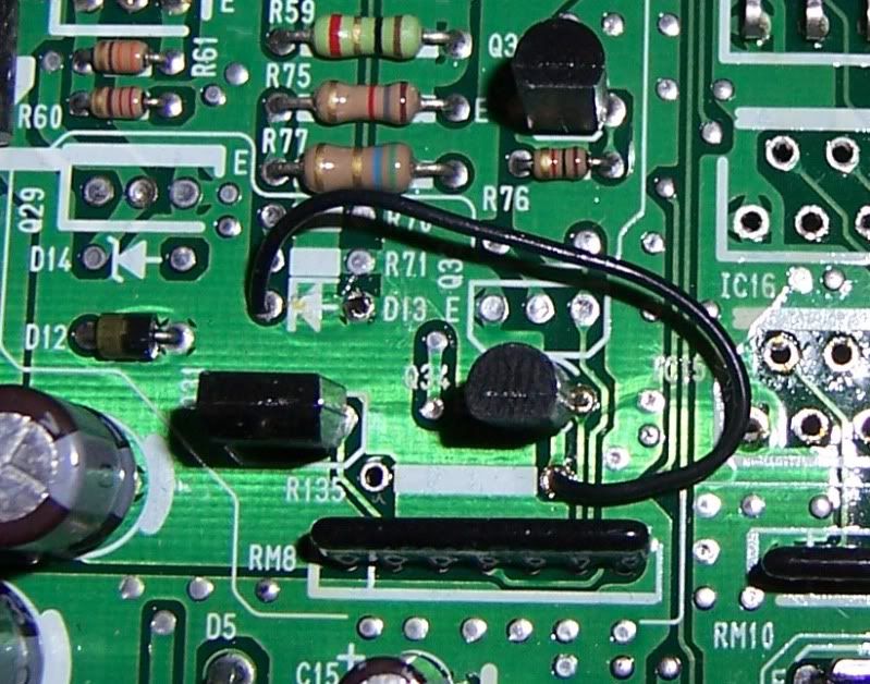
    Add TVIS/IAB functionality (from the PGMFI wiki):
    - Q17(A143)...already present on USDM auto 11F0/1720 (A5x, L5x, etc). Not present on EDM auto 11F0/1720 (G5x, etc).
    - Q34(D1780 or C3225?)... already present on USDM auto 11F0/1720 (A5x, L5x, etc). Not present on EDM auto 11F0/1720 (G5x, etc). May use PCS trans: Q31(D1780)
    - Jumper from right hole of R135(trans side) to D13(arrow side):


    There are more mods listed in the wiki, such as adding the VTEC hardware (staged fuel injection, antilag, etc) and modding other ECUs like the P05.
    PGMFI hardware mods WIKI

  3. #3
    Forum Member 1st year Apprentice
    Join Date
    Feb 2009
    Location
    MN
    Posts
    23

    Default Re: DIY inexpensive engine management

    DISTRIBUTOR MODIFICATIONS:

    Basically, we need a method of feeding the ECU the proper timing signals so it knows where the engine is. The bottom 3 traces on this scope capture show the signal after it's digitized by the HIC1 board, inverted by IC10 and sent to the MCU:


    Of the bottom 3 traces, the top is the TDC signal, the middle is the CKP and the bottom is the CYP.

    As I mentioned earlier, the toyota distributor is essentially wired backward. The honda HIC1 board takes the VR sensor signal and converts it to a 0-5v square wave :

    it's then sent to IC10 where it's buffered/inverted for the MCU.

    The signal dips below ground first, which turns the signal on, pulling it low (logic 0). when the signal crosses zero, the signal releases ground returning to 5v (logic 1).

    Below is a waveform of what the output of the HIC1 board would look like with the toyota signal (falling edge crossing) going through it:


    Basically, it takes too long for the signal to turn off to be re-triggered. Any subsequent pulses would be ignored by the circuit, which would result in missed sync pulses, etc. The 24 tooth signal would still trigger the circuit at the right frequency, but the output would be 180* out of phase- meaning the signal would go low when it should be going high, etc.

  4. #4
    Forum Member 1st year Apprentice
    Join Date
    Feb 2009
    Location
    MN
    Posts
    23

    Default Re: DIY inexpensive engine management

    So, the easiest method- at least the method that everyone who has done this swap thus far has employed- is to install the Honda distributor on the 3SGTE head.

    The modifications aren't particularly difficult. Essentially, there are 3 changes made:

    1. The shaft that inserts into the head is too large. It is 32mm in diameter, and needs to be turned down to 27mm. The first one i did, i used a dead distributor cap and attached a screw to the middle of it to be able to turn it with a drill. Clamped the other end into a vise and spun it while using a cutting tool to remove material. It was crude, but effective. Turns out, the proper diameter for the 3SGTE head is the diameter of the inside of the o-ring groove. Now I just clamp it in a cross-slide vise on my drill press and use a cutting bit while I turn the housing by hand. Much faster and more accurate.


    2. The mounting hole needs to be enlarged toward the center of the housing.


    I originally used a die grinder to ream it out, but I've found doing that on the drillpress to be easier, faster and more accurate as well. I do it sort of the same way I cut the shaft- clamp it down and rotate by hand with a cutter down inside the hole. I also expand it a little side to side for more timing adjustment.

    3. An adapter needs to be made to lengthen the inner shaft to reach the 3SGTE camshaft, and orient the cam key to the engine.


    The adapter needs to be oriented so that the tooth on the top wheel lines up with the sensor when the rotor contact is halfway between TDC #3 and TDC #4. Drill the pin hole, pin the adapter to the shaft and you're ready to bolt it in.

    This is a completed distributor:


    This method requires longer spark plug wires. I'll post below how to disassemble the stock wires and attach them to longer ones.

  5. #5
    Forum Member 1st year Apprentice
    Join Date
    Feb 2009
    Location
    MN
    Posts
    23

    Default Re: DIY inexpensive engine management

    THE ALTERNATIVES:

    I've been mulling over alternative methods of feeding the ECU the correct timing information for a couple years, but the car runs so damn well as-is that I really haven't had the ambition to try going a different direction with it. I'm going to try it this spring.


    The first method involves a translator board. The idea is to use the 24 tooth wheel as a clock signal to a CD4017 decade counter (see http://www.doctronics.co.uk/4017.htm for info on how these work) that waits the proper number of Ne tooth counts to output the CYP and TDC pulses. The G1 signal would sync the board to the engine. This would allow the use of the stock Toyota distributor. Unfortunately, I'm not an EE, and I will need to do some serious testing to make sure the circuit works. I have some ok simulation software, but I don't have the proper component files to draw the circuit to see how it responds to inputs. This may come out eventually, since it would be far and away the easiest means to accomplish the swap- desolder the HIC1 board and replace it with the translator.

    The other method I've been considering is to re-drill (or make custom) the key on the end of the distributor to sync the G1 signal with the CYP signal (moving it from near #1 TDC to halfway between TDCs of #3 and #4). A simple opamp circuit is used to invert the voltage signal from the Toyota sensors to work with the Honda's interface board. The only thing missing at that point is the TDC signal- a falling edge coinciding with each cylinders TDC event.

    That's where the GM DIS module mentioned earlier comes in. The ECM reference pulse is almost identical in both voltage and phase to the digital TDC signal. The Honda ECU can be interfaced with the GM trigger line (can't remember offhand whether it's rising or falling edge- pretty sure the Honda signal needs to be inverted to a falling edge trigger) easily. All that needs to be done is to notch the crankshaft pulley and install a GM crank position sensor to read it. The module is now our new distributor

    The pulley is notched like this:

    (image borrowed from the DIS section of the megamanual)

    The sync/7th pulse occurs 70 crank degrees AFTER TDC of #1/4. I'd mount the sensor first, mark on the wheel where it sits at TDC, then find the proper positions of the notches relative to the sensor.

    The crank position sensor can be mounted to the oil pump bolts like the electromotove crank trigger kit, as the bracketry is not particularly complicated:

    (image borrowed from www.turbomr2.com)
    GM crank position sensors can be found new for as low as $16.

    The module wiring is as follows:
    3 pin connector
    YELLOW= crank sensor
    center/bare= sensor shield ground
    PURPLE= crank sensor

    2 pin connector
    PINK/BLACK= module power, switched 12V
    BLACK/RED= module/reference ground (connect to ECU ground)

    6 pin connector
    PURPLE/WHITE= ECM reference, connect to IC10 pin 3 in Honda ECU. This inverts and buffers the signal before it's sent to the MCU.
    WHITE (inner)= IGT signal
    TAN/BLACK= Bypass. This is grounded while cranking, and pulled to 5V when running. This pin, when grounded, locks the module's timing to 10*. An RTL inverter like the ignition module interface in the first post with the starter signal feeding the base will run this pin.
    WHITE (outer)= Tach signal. I haven't been able to find any info on whether the GM tach is a square wave or inductive kick (like ours). The MR2 tach has been modded to run off a 12V square wave though. There's info on how to mod the tach to run off that signal in this thread: http://mr2oc.com/showthread.php?t=375970

    The bottom metal surface MUST be connected to a good ground. The main power ground goes through this surface.

    So the above setup would have us running the distributor only as a cam sensor, and the GM DIS ignition as the distributor.

  6. #6
    Forum Member 1st year Apprentice
    Join Date
    Feb 2009
    Location
    MN
    Posts
    23

    Default Re: DIY inexpensive engine management

    MODIFYING/REBUILDING IGNITION WIRES

    This is how to modify the plug wires for the longer reach necessary with the Honda distributor. You'll need your stock wires, and a set of wires for a Honda Civic, Accord, Prelude, Integra, DSM (these are uber-long, plenty of material to work with)- whatever you can find a good deal on. NGK wires work very well.

    This is also useful for anyone needing new wires. No need to buy a new set of wires for $80-100, when you can just buy some MSD bulk wire and rebuild your originals.

    The process below took me about 5 minutes for a single wire, with picture taking.

    This really all you'll need:


    1. Separate the upper seal from the plastic tower.

    The OEM wires are glued together where the wire enters the rubber seal. Use a small screwdriver to separate the glue, or just pull on the boot until it comes off the tower. Keep pulling and the glue will separate from the wire (sometimes turning the boot/seal kind of inside out, no biggie).

    2. Pull some slack through so you can push the spark plug end of the wire out of the tower a little ways to expose the crimp terminal.


    3. Use a pliers to bend back the crimp tabs and the terminal comes off. The wire can then slide out of the tower. You're left with a reusable crimp terminal. Both the stock and TRD wires use the Yazaki terminals like this:


    4. Chop the terminal off your new wire and strip back 1/2 to 3/4" of insulation to expose the conductor core:


    5. Coat the new wire with some soap and slide the plug boot, then the plug tower over the new wire. Push enough slack through so that you can put the terminal on.

    6. Bend the conductor back over the wire and slide it into the terminal, butting it up against the end. Use the crimpers or a pliers to bend the jaws of the terminal back over so that they bite into the insulation and grip the wire:


    7. Pull the plug wire snug through the tower. Note that there is a slot in one side of the top of the tower for the wire to bend through as it goes through the seal:


    Lather, rinse, repeat x 4 and you have a new set of spark plug wires. The distributor cap ends use the same style terminals as the plug side, and disassemble the same way in case you want to use those as well.

  7. #7
    Junior Member Backyard Mechanic gixer's Avatar
    Join Date
    Feb 2006
    Location
    South Australia
    Posts
    272

    Default Re: DIY inexpensive engine management

    Awesome

  8. #8
    Non qualified Domestic Engineer
    Join Date
    Mar 2007
    Location
    SA
    Posts
    785

    Default Re: DIY inexpensive engine management

    Nice!!!!

    I'm slowly doing something similar with a Nissan (from the Aussie Holden VL Commodore) engine management/crank angle senor (in the distributor) system into a 1990 Alfa Romeo 75 (Milano for the Yanky's) V6 that formerly ran a Bosch Motronic 4.1.
    The upgrade would be an even better achievement for the earlier L-Jetronic Alfa's.

    Much like the Honda stuff, the Nissan stuff has much aftermarket support with real time tuning interfacing based on manufacturer quality electronics
    Quote Originally Posted by oldcorollas
    except for a very few exceptions
    "Don't worry what people think, they don't do it very often."

    Daily: Glorified Taxi (F6 Typhoon). Out Of Action: Twin-charged Adub. Ongoing Nightmare: Over re-engineered (not) Alfa Romeo 75.

  9. #9
    Toymods Net Nazi Too Much Toyota river's Avatar
    Join Date
    Sep 2005
    Location
    NSW
    Posts
    7,061

    Default Re: DIY inexpensive engine management

    Hi,

    It's been a while since I've been impressed with something technically rep-worthy.

    Nice work, great write up. +rep

    seeyuzz
    river
    The thinking man's clown and the drinking woman's sex symbol
    RA25GT - There is no substitute | 18R-G - Toyota's Dependable Masterpiece
    Toymods Car Club Treasurer, assistant Historic Plate Registrar & Forums Admin

  10. #10
    Forum Member 1st year Apprentice
    Join Date
    Feb 2009
    Location
    MN
    Posts
    23

    Default Re: DIY inexpensive engine management

    Quote Originally Posted by Duk View Post
    Nice!!!!

    I'm slowly doing something similar with a Nissan (from the Aussie Holden VL Commodore) engine management/crank angle senor (in the distributor) system into a 1990 Alfa Romeo 75 (Milano for the Yanky's) V6 that formerly ran a Bosch Motronic 4.1.
    The upgrade would be an even better achievement for the earlier L-Jetronic Alfa's.

    Much like the Honda stuff, the Nissan stuff has much aftermarket support with real time tuning interfacing based on manufacturer quality electronics
    cool, i'd love to read more about your setup when it's done.

    this was just kind of a detailed outline of how i did my setup, but really any ECU that's been hacked enough to be able to reprogram it to run any engine will work, and there are plenty of them out there.

    the main thing is just figuring out what crank/cam position info the new ECU needs and providing it reliably. i had been working with a GM 7749 ECM before i went with the honda setup and those are ridiculously simple- a single pulse every time a cylinder hits TDC is all that's required, and the same ECU can run 3-8 cylinders.

    i eventually chose honda electronics because i was already familiar with them, and i had a chance to tune a friend's prelude and i was stunned how easy it was. there are a lot of added features as well (launch control, VTEC output can be used for staged fuel injection, boost control, etc) and i'm pretty sure i'll have an ignition demux board worked out here shortly for running coil on plug ignition. the idea is to eventually get rid of the distributor altogether and run crankshaft trigger for the CKP and TDC signals and a single cam pickup for CYP. this would provide much better accuracy at high rpm.

    i've also got a circuit (needs testing) that should be able to read the toyota/mazda 24/1+1 distributor and output the timing info for the honda ECU, so only swapping the board in the ECU, no need for a different distributor. i should work one out that converts a 36-1 wheel too. a single crank wheel and single cam pickup would be very slick.

  11. #11
    Not trying to be a Carport Converter
    Join Date
    Jan 2009
    Location
    WA
    Posts
    1,624

    Default Re: DIY inexpensive engine management

    That's an amazing amount of detail, a lot of which i don't really get! How did you even come to the thought that this could be done, saw the plugs were the same and said "why not?" hehe amazing stuff, thanks for posting with so much detailed info!

  12. #12
    Your mum is a Conversion King TERRA Operative's Avatar
    Join Date
    Mar 2007
    Location
    Chiba
    Posts
    2,232

    Default Re: DIY inexpensive engine management

    Awesome info!

    How would this go with a Gen 4 3SGTE, with the coil on plug system? (no distributor)

  13. #13
    Backyard Fabricator Automotive Encyclopaedia
    Join Date
    Sep 2005
    Location
    QLD
    Posts
    1,103

    Default Re: DIY inexpensive engine management

    So can the honda ecu be tuned in real-time? Or do the changes need to be done offline and flash updated?

  14. #14
    Forum Member 1st year Apprentice
    Join Date
    Feb 2009
    Location
    MN
    Posts
    23

    Default Re: DIY inexpensive engine management

    Quote Originally Posted by TERRA Operative View Post
    Awesome info!

    How would this go with a Gen 4 3SGTE, with the coil on plug system? (no distributor)
    it would require crank triggers. i'm not entirely sure what the gen4 uses, but if its' like most of the other OBD2 era toyota stuff, it's likely a 36-1 crank trigger with a cam sync. the cam sync could be made to work, the crank trigger may require a custom wheel with 12 teeth to get the CKP signal. if i were doing it on a gen4, that's how i'd do it- custom cut a crank trigger and use the stock crank sensor, get the cam sync lined up with where the CYP needs to be and then use either an ignition demux circuit to split the signal out to the coils or run a GM DIS module with plug wires. the GM module would probably give better performance at higher boost than the OEM coil sticks, since COP units are typically fairly low energy.

    Quote Originally Posted by JP
    So can the honda ecu be tuned in real-time? Or do the changes need to be done offline and flash updated?
    yes, it can be tuned in real time. different software folks do things in different ways, but i just use a ROM emulator (ostrich) which allows the software to make changes to the tune while the engine is running. it makes tuning go MUCH faster, but the stop and flash/burn method isn't too time consuming if you have a good strategy for fuel.

    i use an excel spreadsheet that lets me put my fuel map in one section, my logged lambda readings in another and desired targed lambda in a third and it calculates and outputs a whole new fuel map that i just copy/paste into CROME. it takes about 3 pulls to get the fuel nailed down pretty well with this method.

    for ignition, i do a baseline pull, logging rpm vs time. after making changes i plot the next pull against it to see if torque increased in the cells where i made changes. when torque stops increasing with added timing, i back it off a couple degrees and use those cells to extrapolate the rest of the map. my conservative street tune put down 276whp at 12psi on E85 (would have made more, but ran out of fuel pump). it's not as good a method as watching real time torque on a dyno, but it gets the job done to about 95% of where you'd get on a dyno. it's all about being able to measure whether there's actually an improvement or not.

  15. #15
    Forum Member 1st year Apprentice
    Join Date
    Feb 2009
    Location
    MN
    Posts
    23

    Default Re: DIY inexpensive engine management

    Quote Originally Posted by senn View Post
    That's an amazing amount of detail, a lot of which i don't really get! How did you even come to the thought that this could be done, saw the plugs were the same and said "why not?" hehe amazing stuff, thanks for posting with so much detailed info!
    for the most part, i've always been of the mindset that the electronics don't actually know they're attached to an engine, much less an engine of any particular brand. i used to have an integra and i knew how easy those were to tune/hack, and since poverty is the mother of invention, it just kind of happened. i'm not the first to run a 3SGTE on a honda computer, but i'm pretty sure i'm the first to do it in the SW20 chassis, and to do it with most of the stock sensors/wiring.

    i've always thought naming cars was a bit strange, but if i ever did name my MR2 it would have to be called frankenstein, since it's essentially a monster created from cobbled together parts from other dead cars. my ECU/ignition is from a honda, brakes are from a porsche/supraTT (front), fiero/RAV4 (rear), injectors from a WRX, fuel rail from a celica/camry, turbo from a GMC syclone, etc. using parts from other cars is a fantastic way to accomplish specific goals without going broke.

Similar Threads

  1. GUIDE: ISCV Wiring / M-REL Wiring
    By wilbo666 in forum Tech and Conversions
    Replies: 12
    Last Post: 17-07-2011, 03:36 PM
  2. MA70 --> JZA70 Conversion
    By Lambolica in forum Engine & Driveline Conversions
    Replies: 119
    Last Post: 09-09-2007, 08:39 PM
  3. Turbos 101
    By WeekendWarrior in forum Tech and Conversions
    Replies: 5
    Last Post: 24-01-2007, 08:23 PM

Bookmarks

Posting Permissions

  • You may not post new threads
  • You may not post replies
  • You may not post attachments
  • You may not edit your posts
  •