first off i did not take the pics and i did not do the work pictured.
i was e maild this PDF file by a freind who found it on a web site he can no longer find so instead of posting a link ill just make a thread about to make it easy to find view and
critique. and yes i know the pics are upsidown![]()
Standard Drive Assemblies T50 left and AE101 right
Step One:- Dissassembly
T50 Drive:-
Disassembly is simple, remove the “C” clip from the drive housing , just above the drive gear.
This will allow the shaft/gear assembly to be withdrawn from the housing.
Remove the “O” ring from the housing.
Wash all parts internally and externally to remove oil, grease and road grime.
AE101 Drive:-
Disassembly is similar to T50, remove the “C” clip from the drive housing , just above the drive
gear.
This will allow the shaft/gear assembly to be withdrawn from the housing.
Remove the “O” rings from the housing.
Remove the three (3) philips head screws from the cover on the top of the drive housing.
Carefully remove cover, be aware that the small parts in side may be stuck to the cover.
Remove all internal parts, record order of assembly.
Wash housing and shaft to remove oil, grease and road grime.
![]()
Last edited by MitchE; 22-04-2008 at 03:50 PM.
Step Two:- Shortening the Drive Shaft
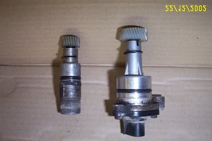
Drive Shaft:-
The T50 drive shaft needs to be shortened to a similar length to the AE101.
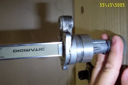
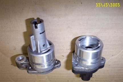
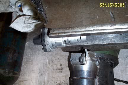
I reassembled the AE101 shaft and housing, and then measured from the top face of the AE101 housing
down to the top of the AE101 drive shaft. (Fig.4) Record this reference depth, (I got 17mm) .
Fig.4 Drive Shaft Depth Std AE101 Shaft & Housing
The T50 drive shaft will need to be shortened to give the same depth as measured in Fig.4.
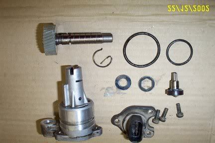
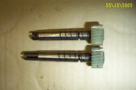
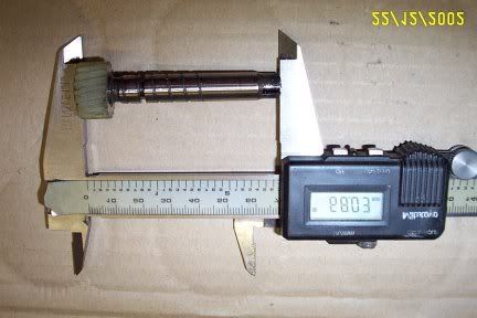
When I did mine, (and a few others), I found I needed the T50 shaft to be 68.0mm long. Fig.5 Fig.6
The drive shaft is hardened, so I used a belt linisher to shorten the shaft, it could as easily be done on a fine grinding wheel.
Remember slowly does it, regular checks of depth in housing and do not let the shaft get too hot during
grinding/linishing, this will affect the heat treatment and consequently affect the strength of the drive dogs on the shaft end.
Carefully deburr and chamfer, end detail should be similar to original AE101.
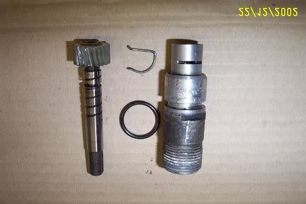
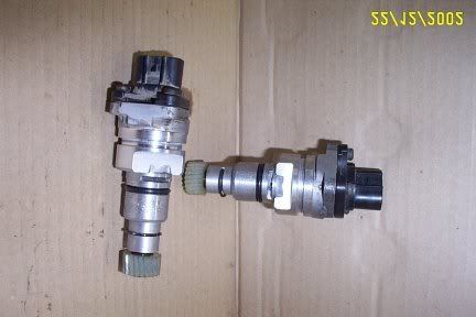
Fig.5 T50 Shaft Before upper and After lower.
Fig.6 T50 Shaft Overall Shortened Length
Step Three:- Modify the Housings
T50 Housing:-
The modifications to the original T50 housing is really only shortening and if necessary a clean up
cut of locating diameter.
The standard housing is chucked and trued up in a lathe, the threaded portion is then turned/parted off.
A 0.5mm chamfer is turned on the outer edge. Fig.7
If the outside diameter 22.2mm (0.875”) is damaged, a light clean up cut should be taken.
Deburr the inside corner.
Fig.7 Standard T50 Housing left Shortened Housing right.
AE101 Housing:-
The modifications to the original AE101 housing is really only shortening and boring out the
lower end to accept the shortened T50 housing..
The standard housing is chucked and trued up in a lathe. Fig.8 (seems to be miising)
The extension part of the housing is turned/parted off, and the remainder is faced to clean up.
The remainder of the housing is bored out to 22.3mm (0.878), for a distance off 11.0mm deep. Fig.9
When boring, a thin synthetic disc will fall out with swarf (shavings), this is a slinger, and may be
discarded.
Deburr the inside corners.
Fig.9 Standard AE101 left Modified right
Last edited by MitchE; 22-04-2008 at 03:40 PM.
Step Four:_ Assembly
This assembly process should be performed “dry” to ensure all modifications have been performed correctly.
After you are satisfied that the work has been done correctly, disassemble, and wash part in solvent, prior to final assembly.
Final Assembly:-
Apply a film of lubricant, light grease or oil will do, to the shortened T50 shaft, insert the
shortened T50 shaft in to the shortened T50 housing and fit “C” clip.
Test fit the T50 housing/shaft assembly to the AE101 housing, ensure that the measurement obtained in Fig.4 is still obtainable.
Apply a thin film of “loctite” 680, 271 or 630 to the modified T50 housing, insert the T50 housing into the
modified AE101 housing until the Fig.4 measurement is obtained.
Set aside to allow the “loctite” to cure.
When “loctite” has cured, apply a thin film of lubricant to the inside of the AE101 housing, and to all AE101 parts.
Reassemble the AE101 driven shaft, thrust disc, hex disc and “O” ring and then fit cover and 3 phillips head screws.
The only remaining job is the machining of the clearance flat on the AE101 housing.
This flat is required to allow clearance to fit the retainer plate and bolt when the new modified assembly is installed in the T50 extension housing.
I held the completed assembly in the vice of my milling machine, and milled a flat as shown in Fig.10 .
This could just as easily be done with a good sharp file.
Deburr all corners,.
Replace “O” ring in T50 part of housing.
New drive is ready to go.
Fig. 10 Milling Setup
Fig. 11 Completed Drives
well thats all of it it made sense to me when i went through it and it seems all of the measurments are there so you could take your parts and measurments to a maching shop withuot to many dramas.
(if anyone knows who made this do tell me and i will edit their name into the top post)
mitch
Mitch, just to give Paul Hannell credit where it's due and in case the above images are lost, here's a link to his original document covering this mod
http://www.locost7.info/files/gearbox/T50SpeedoMods.pdf
GSE20 IS250 - daily
UZZ30 Soarer - 1UZ-FE/R154/Adaptronic - trackday roughie
UZZ32 Soarer - Active Hydropneumatic Suspension (A-SUS) & Active Four Wheel Steering (A-4WS) - cruiser