
 Reply With Quote
n00b question here:
so you need the transistor because the 3v from Fc is not powerful enuff to trigger the relay on its own?


So I was wiring up the fuel pump relay on the sprinter, whilst musing on how many toyotas are getting around with the fuel pumps hard wired to swithches or ignition power etc.
I think this is mainly due to some misinformation circulating and a general fear of electronics.
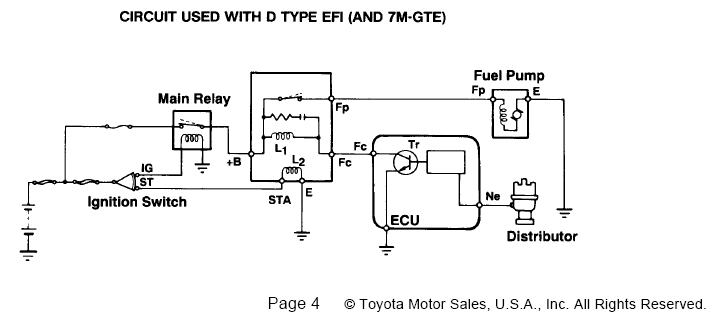
Anyway, if your toyota ecu has an Fc pin (usually on the plug with main power feeds etc.) it will switch on when cranking, and when the engine is running; so there is no need for secondary relays.
This pin (on every toyota ecu I have encountered) will supply a +3v signal whenever the fuel pump is required, contrary to some writeups which claim that it is a ground signal.
The circuit pictured below only requires four components: relay, 2 resistors and a transistor, which all up cost around $10 from Jaycar or similar. It consists of a voltage divider to convert the +3v signal to a +1v logic signal for the transistor, and the transistor itself to pull the coil of the relay to ground. THe actual transistor used is not really important, only that it is relatively heavy duty and of the NPN variety. The part no. I used is there for a reference if you don't know what you are looking for.
Anyway, heres the circuit, pretty self explanatory:
This is a really far out, witty and clever signature.

n00b question here:
so you need the transistor because the 3v from Fc is not powerful enuff to trigger the relay on its own?
- ma61 + 2jz-gte + v160 + 3.5 torsen
Can you tell me what ECUs have a FC pin that isn't an open collector output? (i.e. NPN)
I think you are wrong, and should stop spreading incorrect information
And I have some Toyota documents that back me up in saying you are wrong
I.e.
And try reading this doc (among the others on autoshop101.com)...
http://www.autoshop101.com/forms/h22.pdf
Also THIS thread is a much better guide to the Circuit Opening relay.
http://www.toymods.net/forums/showthread.php?t=18471
Cheers
Wilbo
Why not just wire it as factory? It's not that hard and Toyota circuit opening relays are free and abundant from self serve wreckers...
Transistor should have a current limiting resistor and a reverse-biased shorting diode across the relay coil to prevent the transistor burning out and being killed by back EMF.
You are wrong, or have encountered ECUs with blown outputs. How many have you encountered?Originally Posted by nb86
My AE86 4AGE ECU had the FC output blown as well, with the internal transistor blowing with a short from the base to the collector, so the signal was still passing through to the FC pin, albeit a 5V with associated source resistances. I did something similar to you to get the output running.
As wilbo stated, Fc is an open collector output on *EVERY* toyota ECU. This is a well understood fact. It wouldn't hurt if you acknowledged this so that you're not spreading misinformation.
There is no divider in your circuit. The 1k resistor does nothing when the 3V signal is present - it is only there to pull the base of the transistor to ground when the 3V signal is removed, to discharge any capacitances on that line - it would work without it.
The 2k resistor is the base current limiting resistor - it drops the voltage to whatever the VBE is at whatever base current it pulls, and has nothing to do with the 1k resistor.
On the other hand, if you had the 1k connected to the base of the transistor...
On the base only (which it does have).
It does not need a current limiting resistor on the switching side - the transistor should be chosen with a suitable current rating such that the current of the switched circuit does not exceed the rating.
Yep.
Mos.
Admin, I.T., Founding Member, Toymods Car Club Inc.
2000 IS200 Sports Luxury 1UZ-FE VVTi, 1991 MX83 Grande 2JZ-GTE (sold)
[QUOTE=Mos]On the base only (which it does have).
It does not need a current limiting resistor on the switching side - the transistor should be chosen with a suitable current rating such that the current of the switched circuit does not exceed the rating.[QUOTE]
Ah yea. been a while (and was late...)
 Posting Permissions

Bookmarks