Results 1 to 4 of 4

Thread: Aristo JZS147 Turbo Timer Install (Part 3 in a Series)(Lotsa Pix)

  1. #1
    Junior Member Automotive Encyclopaedia infotechplus's Avatar
    Join Date
    Apr 2006
    Location
    NSW
    Posts
    816

    Default Aristo JZS147 Turbo Timer Install (Part 3 in a Series)(Lotsa Pix)

    In this episode I am going to install an FET TB-308 fully automatic Turbo Timer in my Aristo. It's a 1996 Series 2. Whilst not all Turbo Timers have the same wires and functions this will still be a useable "How To" for anyone with an Aristo.

    This Turbo Timer has been around for at least 10 years and there is very little information on it around the web but after some persistent searching I found that it was using the following wires:

    FET TB-308

    Red - Battery (constant 12V)
    Yellow - Ignition 1 (Key is in ON position)
    Blue - Ignition 2 (Key is in ACC position)
    Black - Gnd
    White - Handbrake

    To wire it up correctly I used the following from the ignition harness

    Black/Red wire - Constant 12V (Red on TB308)
    Black/Yellow wire - Ignition 1 (Yellow on TB308)
    Brown/White wire - Ignition 2 (Blue on TB308)

    Plus

    White wire on TB308 to Green/White wire on the handbrake switch
    Black wire on TB308 to Earth

    I found using the Blue/Red wire on the Ignition switch, whilst it is ON when you turn the key to ACC, didn't allow the engine to stay on when you turned the ignition off (even though it had 12V + like the Brown/White wire).

    PS. There are two Brown/White wires on the Ignition switch. You want the wire at the back near the blue wires.

    I've driven with this Turbo Timer installed for a couple of days, and I have it set to the automatic position (Mode 2) where it adjusts the time according to how you drive.

    Here's how it works:

    The power button turns the unit on/off

    The set button changes between the 3 modes.

    The first and second modes are both auto where in the first mode the idle time rises at a much quicker rate than the second mode depending on how the car is driven.

    The third mode i never use (manual set), but if you hold the set button when you're on "auto2" you'll be able to change the idle time on the third mode in increments of 50 secs.

    Tools needed

    Long handle screwdriver
    Sidecutters
    Stanley knife
    Electrical tape
    Soldering iron
    Turbo Timer harness (I made up my own)
    Convoluted or spiral tubing
    Electric light (to illuminate under the dash)

    Time Required:

    About 1 - 2 hours depending on how proficient you are with a soldering iron

    DON"T FORGET TO REMOVE THE BATTERY CABLES

    In the next post we'll get started

    Cheers,

    Peter
    Last edited by infotechplus; 24-03-2008 at 08:21 AM.
    OMG - Winner of the Official "Forum Comment of the Week"!

  2. #2
    Junior Member Automotive Encyclopaedia infotechplus's Avatar
    Join Date
    Apr 2006
    Location
    NSW
    Posts
    816

    Default Re: Aristo JZS147 Turbo Timer Install (Part 3 in a Series)(Lotsa Pix)

    Part 1: Getting access to the ignition wiring

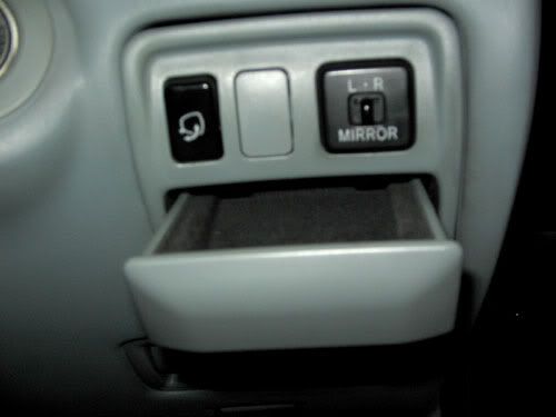
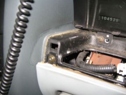
    I started by pulling out the coin drawer on the right side of the dash. There are two screws holding it in underneath. Remove these.


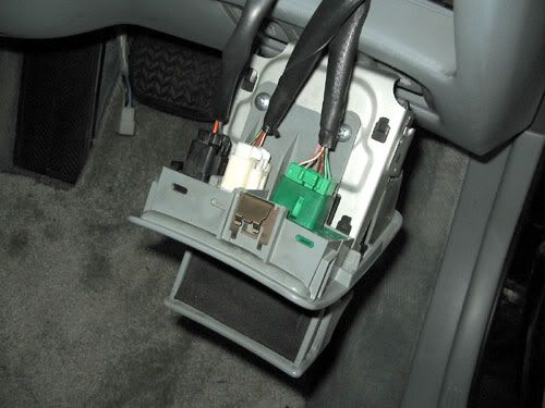
    With the coin drawer fully out, unclip the three harness plugs and put the drawer aside


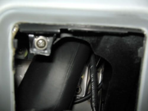
    Now there is a single screw to remove on the left of the drawer opening


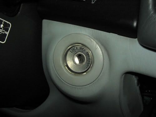
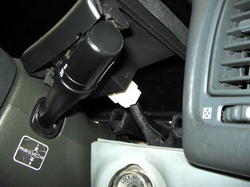
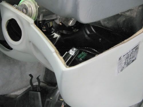
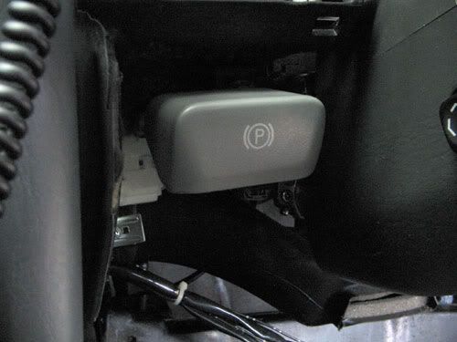
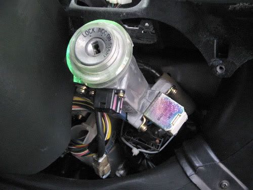
    Next I removed the surround on the ignition key. It just pops out and you can remove it by hand without too much trouble.


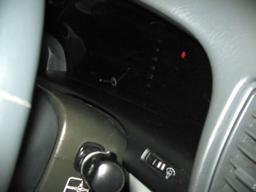
    Now remove the black dash piece in front of the instrument cluster.


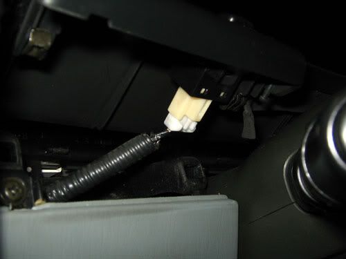
    It pops out as it is only held in by clips. Use your fingers to gently pull up from the back - it should pop out. Go easy as you have to remove a wiring harness from each side

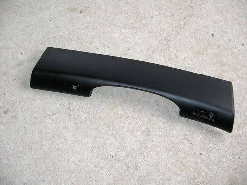
    Right side (Light adjuster)


    Left side (TRC on/off)


    Put the piece safely to one side (eg. on the back seat, out of the way)


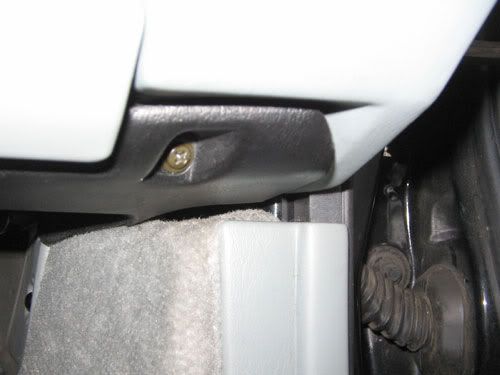
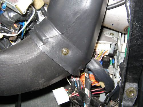
    Removing this piece gives access to a screw on the left side of the dash. Remove this.


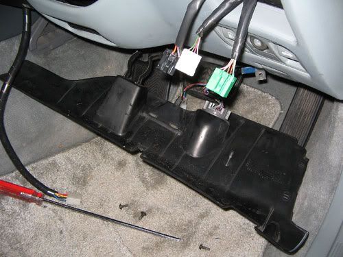
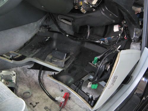
    That takes care of most of the top side. Next we'll move to the bottom trim.
    Last edited by infotechplus; 24-03-2008 at 08:41 AM.
    OMG - Winner of the Official "Forum Comment of the Week"!

  3. #3
    Junior Member Automotive Encyclopaedia infotechplus's Avatar
    Join Date
    Apr 2006
    Location
    NSW
    Posts
    816

    Default Re: Aristo JZS147 Turbo Timer Install (Part 3 in a Series)(Lotsa Pix)

    On the underside of the dash there is a black trim piece held in by three screws - one on each side and one in the middle. This cover holds the courtesy light and the AC vent under the steering column. Here's the right side screw.


    All screws removed, let the trim hang down.


    There are a couple of screws on either side holding the larger trim panel on. Remove these and you should be able to gently pull it up and out. This photo also shows the clips that are used to hold the panel.


    On the left side you have to clear the handbrake lever and the steering column adjustment knob.


    Put the panel on the floor out of the way. I didn't remove any of the plugs as it wasn't really in the way for what I needed to do.


    Wiring It Up

    We now have access to the ignition wiring (well, almost)

    You need to use the sidecutters to cut the cable tie and allow the harness to drop down where you can work with it.


    To give yourself a bit of room remove the AC tubing that runs across the dash from the centre. This one screw is all you need to remove and then gently pull the plastic tubing out.

    Last edited by infotechplus; 24-03-2008 at 08:40 AM.
    OMG - Winner of the Official "Forum Comment of the Week"!

  4. #4
    Junior Member Automotive Encyclopaedia infotechplus's Avatar
    Join Date
    Apr 2006
    Location
    NSW
    Posts
    816

    Default Re: Aristo JZS147 Turbo Timer Install (Part 3 in a Series)(Lotsa Pix)

    The tubing has been removed and placed aside.


    I unplugged the harness to do a search and test on the wiring. There are a couple of other tutorials floating around the Net but I found them to be not quite right. As I said in the opening post, you have to use the Brown/White wire for IGN2 not the Blue/Red wire. Both respond to the test light with the key in the ACC position but the Blue/Red connection doesn't route the signal needed by the Turbo Timer to keep the engine alive.

    You need to use the Brown/White wire at the back near the two Blue wires.


    This is the harness I made up to connect the Turbo Timer to the ignition wiring. You can get the kit from any electronics store (JAYCAR, etc). It makes it handy to be able to plug/unplug the Turbo Timer if you need to and not disturb the ignition wiring.


    I connected the handbrake safety wire to the switch to the left of the dash. You don't have to remove the wiring but that white plastic housing pops off, giving you a bit more room to play with. I spliced the wiring and soldered it, then wrapped it in electrical tape.


    The trickiest part is using the Stanley knife to cut away a little of the wiring insulation. It's not too bad as these wires a quite thick.


    I applied a little solder to each of the three wires, then tinned the harness wires, and joined them up. Make sure you get a good join here as you don't want a dry joint down the track! After doing each wire, wrap the joins in electrical tape.


    I then wrapped the complete harness and used a new cable tie to put it back under the steering column.

    The last part of the job is the connect the black wire to an effective ground point. I put a ring terminal on the wire and bolted it to a point on the transmission tunnel. To do this I removed the air vent and pulled the carpet aside. There is a 12mm bolt there that will do the job!

    Putting everything back together is the reverse of what we have done. Take your time and you shouldn't have any screws left over.

    I mounted the Turbo Timer under the handbrake handle. It's a good spot, out of the way, the surface is quite flat and I used extra strength double-sided tape.

    RECONNECT YOUR BATTERY AND TEST.

    Tip: Use Wax & Grease Remover to clean the mounting position. This will allow the double-sided tape to really adhere to the panel.


    Now you can enjoy your labour and keep your Aristo's turbos in better shape (hopefully)

    Cheers,

    Peter
    Last edited by infotechplus; 24-03-2008 at 08:49 AM.
    OMG - Winner of the Official "Forum Comment of the Week"!

Similar Threads

  1. Aristo JZS147 Stereo Install (Part 2 in a Series)(Lots of pix!!)
    By infotechplus in forum Tech and Conversions
    Replies: 15
    Last Post: 14-04-2008, 10:03 AM
  2. Aristo JZS147 Stereo Install (Part 1 in a Series)
    By infotechplus in forum Tech and Conversions
    Replies: 11
    Last Post: 24-01-2008, 11:57 AM
  3. Stock/Standard JZS147 Aristo Battery CCA Rating?
    By Esteban in forum Tech and Conversions
    Replies: 5
    Last Post: 09-10-2007, 07:40 AM
  4. 2TG Turbo Upgrade - Advice/help please
    By scottsta22 in forum Tech and Conversions
    Replies: 14
    Last Post: 22-01-2007, 11:12 PM

Bookmarks

Posting Permissions

  • You may not post new threads
  • You may not post replies
  • You may not post attachments
  • You may not edit your posts
  •