Results 1 to 10 of 10

Thread: TUTORIAL: How to build a 'cheap' 5S-GE motor from 5S-FE

  1. #1
    Dude with a spanner Grease Monkey bajachris88's Avatar
    Join Date
    Apr 2007
    Location
    QLD
    Posts
    88

    Cool TUTORIAL: How to build a 'cheap' 5S-GE motor from 5S-FE

    I just published and posted a tutorial for those interested in a cheap 5s-ge up on celicatech... Thought you might be interested as I was a poor soul that didn't have this info readily available. enjoy

    ------------------------------------------------------------------------------------------------------------------------------
    How to build a 'tight arse' 5sge motor out of ur 1990 5sfe celica (Australian) using your stock 5sfe ecu and wiring loom.
    Written by Christopher James Leete. ([email protected])


    INTRO:

    Before reading or attempting, I am not responsible for what you do to your car. This will tell you how to do it, but if anything goes wrong feel free to ask and I will happily help you out if i can. BUT i'm not accountable for any damages, losses or injuries. Do this at YOUR OWN RISK. Now that i have removed any legal liability, let me tell ya....

    5sge conversion is NOT HARD. All the hard work is here. It is just VERY TIME CONSUMING. Researching and experimenting how to do it was the hard work. This will tell you how to make everything match. Its not in the greatest of detail, but if you need more information, just ask. I have wrote this document so no other poor sucker gets thrown into the deep end with "how the hell do i do this?". There is limited information available into how to make this engine combination. Sure there is heaps on how to bolt the head down, but thats just the start.

    This is a quick overview tutorial into how to turn your 1990 5sfe powered celica into a 5s-ge motor using a 1986 st162 3sge head. This tutorial explains how to do the 5sge setup using the original 5sfe ecu and wiring harness. Compression ratio will be slightly less as a result, however overall with the desposal of the 5sfe fuel economic head, overall performance throughout the rev range is achieved. YOU WILL NOTICE A PERFORMANCE INCREASE AND FAR BETTER POWER CURVE. This is a good street setup, however if you were keen for serious professional track work, consider an aftermarket ecu, high compression ratio pistons, forged internals etc etc to increase the rev red line and HP for a high performing naturally aspirated setup. However this 'tight arse' setup is pretty darn good for a bit of fun on the streets or for a recreational fun spin on the track. I did it and i believe it was worth every cent and minute spent. After driving the 5sfe for 18 months, i wanted a bit of an engine upgrade and thats what i have achieved. This is my personal opinion. Anyone can disagree and cricise but as the owner and builder of a 5sge I stand by it, AND LOVE IT. Hey, atleast you can now gloat u don't have a camry motor .

    The original 5sfe ecu does not seem to inhibit the performance or workings of the 5sge motor. However with an aftermarket ecu one could taylor the ignition advance curve perfectly to squeeze as much horse power as possible. There is no worries with running too lean or rich, as the ecu with the oxygen sensor in the exhaust works with the extra air flow with the 3sge head by sensing the emissions produced and (along with the throttle position sensor) controls the injectors appropriately to maintain the approximate healthy fuel to air ratio programmed into the ecu. It all works, so don't fear. Pretty much all the 5sfe sensors are different to the 3sge, however this document tells you how to adapt each of the 5sfe sensors to the 3sge. This includes the sensors on the manifold itself, throttle, distributor, water outlet and oil senders. One of the benefits with the stock 5sfe ecu computer setup is that you can't get yourself into too much trouble. Although there are ways of destroying your engine that the computer can't prevent, it does come with some form of a 'FAIL SAFE' setup, based on whether sensor readings are too unusual or not even present. If unusual or there is no signal from a sensor, the engine either shuts down or runs based on a 'safe mode' setup. This involves ignoring the unusual or awkward sensor readings and running off a pre-stored signal in the ecu memory that is typically a normal signal off the type of malfunctioning sensor. Those toyota engineers were pretty switched on.

    Many forums have provided misleading information, along with forum users providing irritating, time wasting, incorrect details. Fitting the head to the block is one thing (and the easiest thing to do), but getting everything else to work with the head was a mission. There was no decent information available, pieces of the puzzle were scattered everywhere far and wide. Many weeks of research had to be done. I have condensed all my research into this document to make it as easy as possible for any future 5sge builders and for them to know what they are up against. Its a million times easier now with this 'how to' document i have produced so don't be put off by my rant. But i just wish i had this before i started. Would have saved me many hours, blood, sweat, tears, tantrums, 3 throttle bodies and 4 distributors and my hard earned money haha. (alot of experimenting went on for best possible, least bodgey solutions. This included alot of trials and mix and matching, modifying etc).

    PLEASE READ ALL BEFORE ATTEMPTING TO KNOW WHAT YOUR UP AGAINST. HAVING A WORKSHOP OR PROFESSIONAL MECHANICS FOR MATES ALWAYS HELPS IF YOUR NOT THAT MECHANICALLY MINDED. THOSE WHO HAVE NEVER CHANGED A HEAD GASKET BEFORE CAN DO THIS (Celica repair manuals can help you step by step through the removal of your 5sfe head). BY THE END OF IT, YOU WILL PRETTY MUCH KNOW HOW TO REFURBISH A HEAD, REBUILD A THROTTLE BODY AND REBUILD A DISTRIBUTOR.

    Oh, and don't do this to your daily driver unless you are able to afford having it off the road for a 'decent' period of time. Although it may not take you this long, but a month at the least is the best security. It all depends how many hours you can afford to put in.


    MATERIALS:
    --------------------------------------------------------------------------

    Parts:


    1 x complete 3sge head (1986) (complete with cams, cam gears, valves, lifters, the lot!, oil switch, rocker covers everything you can score from it)
    1 x 3sge timing belt covers (should be 3 covers in total, 3 meaning 2 outside covers and 1 backing plate)
    1 x 3sge timing belt and tensioner (with spring)
    1 x brand new set of head bolts
    1 x 3sge water outlet (go to wreckers) with all the pipe fittings from the 3sge water outlet still attatched cause some different pipe shapes will be required. Try and score the hose clamps too, can never have too many.
    1 x VDO adapter to adapt smallest 5sfe coolant temp sender into one of the 3sge coolant sensor mounts on the 3sge water outlet (you will know which of the many mounts to adapt it to when you get to this stage)
    1 x 3sge intake manifold (including the tvis butterflies, again score as much of the parts off it as you can)
    1 x 3sge complete throttle body (from wreckers) (with no electronic ISC valve. You will see underneith, its got no wire plugs for an ISC, only for a throttle position sensor. Pretty sure you will only find this type on the early st162's rather than the late. Say 86' model)
    1 x Your current running and healthy 5sfe (healthy block more importantly, if the top end is sick, it will be disposed of anyways)
    1 x 1990 GT4 (or alltrac for the U.S) distributor. The 1990 3sge distributor might be suitable, but i wouldn't know, Australia didn't get 3sge powered st184's (Make sure the dissy matches ur stock 5sfe setup, ie: with or without inbuild coil/ignitor)
    1 x 3sge ignition leads
    1 x 3sge alternator mount, tensioner and alternator belt.
    (MAYBE) 1x thread adapter to fit 5sfe oil switch where 3sge oil sender goes (Again, read on for details).

    Misc:

    1 x 3sge VRS set
    Tube of Selleys silicone gasket maker
    Locktight glue/adhesive (quick dry is always better)
    Degreaser
    Sandpaper (240 grit at the roughest)
    Bucket of spare nuts, bolts and washers always help
    5 ltr tub of 20W50 Oil
    Fresh oil filter
    Type A green coolant (anti-boil, anti-freeze, anti-corrosion). NOT type B. Can be premixed or get concentrated and a bottle of distilled/demineralised water.


    Tools:

    Spanners (ring and open)
    Stanley knife
    tin snips (or just use a grinder)
    Timing light
    Sockets
    Bench vice
    Flat head and philips head screw drivers
    Torque wrench
    breaker bar
    Electric drills and assorted drill bits (appropriate for drilling through metal)
    brench grinders
    Angle grinder
    wire brushes (both hand held and power drill types)


    --------------------------------------------------------------------------

    Prodedure:

    (NOTE: refering to your current service manual, whether it be Haynes or otherwise, is a great help to the removal of your current 5s-fe cylinder head. Although i really don't like the Haynes. Practically useless manual for anything but engine work.)

    1) remove your 5sfe throttle body, intake, timing belt and cylinder head. It helps to label the leads and tubing, but to match it to the 3sge head can make the labelling useless on most occasions. It may prove useful to you though. You can always refer to vacuum line and coolant line diagrams later on to help in the 'plumbing' mess. Follow the service manuals for the proper methods of removing the cylinder head.

    2) Take your second hand 3sge head to a professional head shop for a shave/polish to make sure your head's flat surface is perfectly flat for mating onto the 5sfe block. It needs to be perfect. Sanding any old gasket material or filing the head is destructive and damaging, get it professionally done. If you are unsure as to whether the head was removed from a running engine... or you are not sure on its present condition, request a full inspection to see if its still useable. NOTE: Each valve has a chrome looking cap on top. It contains shims that make sure the valve clearances with the rocker arms are all in the their proper healthy range. These are specific to each and every valve.... so don't mix them! Number the tops of them with a felt pen or marker if you do remove them.

    3) You need to match you 5sfe ecu sensors to the 3sge components to maintain the use of the old 5sfe ecu (if you don't want the expense and trouble of an aftermarket system). Your 2 main concerns are the sensors on the throttle body, the water outlet and the distributor. Heres how to deal with them:

    A) THROTTLE BODY:


    The 3sge throttle body has a larger diameter barrel compared to the 5sfe. However, its throttle position sensor is also different. From memory, it was 3 prong, rather than 4. We need to adapt the 5sfe throttle position sensor on this throttle body. Before pulling it apart, try to memorize how the spring system works to close the butterly. Its not the most simple setup. If you forget, u just gotta spend some more time nutting it out. Dismantle the 3sge throttle body. You will notice the 3sge throttle position sensor is moved with the internal shaft inside... that also moves the barrel butterfly. remove the 3sge butterfly but unscrewing it from this shaft. You may have to drill out the screws if they are seized. Remove the 3sge throttle shaft. You might need to tap it out if its tight and doesn't want to move too much... Get a hammer, give it a whack without breaking it.... or drive it out with another rod of some sort...

    Dismantle your 5sfe throttle body. Pull the 5sfe throttle shaft out, and compare it to the 3sge. You will notice due to the difference in butterfly diameters, the 3sge butterfly won't fit the 5sfe. We will make it fit... Get a hacksaw blade or similar... and continue cutting both up and down the shaft inside the groove of the 5sfe throttle shaft to fit the 3sge butterfly in... If its a messy job, don't worry... as long as we seal it air tight after the butterfly is in with silicone sealant... air won't uncontrollably pass through into the manifold (what we obviously don't want). Try to prefit the 3sge butterfly into the new groove of the 5sfe shaft. If the bolt holdes for the 3sge butterfly match the 5sfe bolt holes in the shaft, you know the butterfly is centred centred... excellent work!

    With the 5sfe shaft lightly oiled, Get your 3sge throttle body and push the 5sfe throttle shaft in... you might need to give it some (not too harsh) pushing persuasion with a hammer, sometimes they can be a bit of a firm fit... Rotate the throttle shaft so you can now slide the 3sge butterly in... once you do... get some silicone sealant on you finger and rub it into any rough or excessive cutting spots in your shaft... even fill in the bolt holes (that hold the butterfly on the shaft) with silicone. Before the silicone dries, get 2 appropriate sized pop rivets, and stick em in those holes! Fasten those pop rivets in (by obviously poppin them!) and that butterly should be firmly in place. Tidy any excess silicone mess, and make sure its pretty well sealed shut when the butterly is closed... Congrats.. you have a 3sge throttle with 5sfe throttle shaft. This now means you ahve the appropriate drive at the end of the throttle shaft to control the 5sfe throttle position sensor.

    Slide the throttle position sensor on the shaft. You will notice it doesn't sit comfortably because the position of the 2 hold down bolts for the 5sfe throttle position sensor are in a different position to the 3sge sensor. Take the black cap cover off your throttle position shaft and grab your power drill...Be gentle with this position sensor... they are delicate. i went through 2, and I was lucky to have a spare in the back of the workshop. Work out where you can drill at either side of the throttle position sensor to sucessfully mount it securely onto the original 3sge thottle position sensor mounting points (should be 2 screw holes). What you will notice is that the 5sfe throttle position sensor originally had room to move for adjustment on the mounts.... feel free to machine in the same kind of setup to have some slight available movement for future tuning. IF you lined up your holes right, good work, get those 3sge thottle bolts to hole that 5sfe sensor in place. Make sure the sensor is in the correct orientation and not upside down or what not. If the result is messy, don't threat. as long as it works and is solid! Put the protective black cover back on the thottle position sensor... with the new screws in place though, u might have trouble for the cover to sit properly... So feel free to get a stanley knife and carve some clearance into the black cover for these bolts.


    Now, with the bits left of the 5sfe and 3sge, try to fit to accelerator cable mount back onto the 3sge throttle body. It was a mission initially, because it tool a while to recall how the throttle return springs where positioned. the 5sfe and 3sge accelerator cable mounts are quite alike, use either that you see fit... u just need something that will turn in the right direction (when pulled by the accelerator cable) and will return all the way back to fully close the butterfly. Note the bolt that goes on the end of the throttle shaft can't be too tight otherwise it will be too firm to let the spring pull the butterfly back to full close position. If it doesn't fully close, and the spring is all fine... loosen the bolt. If the accelerator cable mount becomes loose... get a tube of lock tight and go nuts to securely fasten the accelerator mount. Just to give a little kick in firmness. Trust me, the stuff works, this ain't no bodgey! If you need more throttle butterfly return power... u can always add another spring to the system. Rather than the kinda coil spring setup it has... see if you can get a normal spring with hooks on either end, one to go over where the accelerator cable mounts into, and the other to mount somewhere on the throttle body or manifold to pull the butterfly back to the close position.

    Now! ISC valve... We can not adapt it. Well not easily... the 3sge throttle body i bought did NOT have an electric one on it. It had 3 water lines going in, a small vacuum line, and one big mega vacuum line. If you have this setup, than i can help you. Block the small vacuum line with silicone. The other lines on the ISC will have available coolant and vacuum lines that can be fitted later on (will be explained later). I couldn't find any publicised information about the non-electronic ISC valve 3sge throttle bodies... However, to keep the stock ecu happy, remove the old ISC off the orginal 5sfe throttle body and plug it in to the wiring loom. Just cable tie this electronic ISC somewhere so its secure just to keep the original ecu happy. I along with my mates at the workshop presume that the ISC in this case, whose purpose is to control the idle speed and adjust depending if the motor is warm or cold, is thermostat based. It opens up a bypass inside to let more air into the intake manifold if the water lines (from the water outlet that plug into this throttle body) are pumping cold coolant.

    Thats all for the throttle body, it is now ready for bolting onto the 3sge manifold. Make sure you preclean and remove the old grime and original gasket material between the contact surfaces, throw in the new paper throttle body gasket from the VRS set and tighten up the 4 throttle body mounting bolts to fit it to the manifold when your ready.

    --------------------------------------------------------------------------
    st185 GT4 309 hp 12.4s 1/4 mile 16psi

  2. #2
    Dude with a spanner Grease Monkey bajachris88's Avatar
    Join Date
    Apr 2007
    Location
    QLD
    Posts
    88

    Default Re: TUTORIAL: How to 5s-ge

    B) WATER OUTLET:


    This is the easy bit. If any of your coolant sensors are broken make your way to the local wrecking yard and remove a 5sfe water outlet with all the sensors attatched (make sure its off the same year 5sfe as yours just to be safe). The price you pay for the whole set of second hand sensors is half that of what you pay for a SINGLE brand new coolant temperature sensor. And if the car was able to be a write off to become a wreck, it means that the car was running and working, and therefore these second hand sensors most likely should have been working, and still should if they aren't crushed. Make sure you use every opportunity to barder at the wrecking yard. Best line of bardering to always throw out, is "Can you guarantee these work?". You would already know the answer, of course they can't. But everytime a wrecking yardie has ummed and arred, or they bring up "hey these coolant sensors are usually worth alot of money, they should be the most expensive", by saying this it has usually turned the game in my favour.

    mount the 5sfe water outlet into a vice clamp. Or just use any method to hold it in place so you can remove every coolant temperature sensor on the water outlet, including the VSV (Vacuum switching valve), which is the blue capped fitting that has 2 hole outlets on it for vacuum lines). Be gentle with them, as the plastic clips to the sensors are delicate. I went through a few in the process. Remove them all as every one of these needs to be transplanted onto the 3sge water outlet (yet again, to keep the original ecu happy). Remove all the fittings from the 3sge water outlet, you dont need any of them. Fit the 5sfe water outlet fittings you just removed into the 3sge water outlet, making sure they are properly sealed either with copper washers or rub a generous amount of Selleys Black Gasket Maker silicone goop on the threads of each fitting. It doesn't matter their orientation of these fittings, fit them into any hole applicable on the 3sge water outlet. What you will notice though, is that one small 5sfe fitting is too small to be fitted into the remaining 3sge water outlet hole left over. (after you screw the other ones in) This is where that VDO adapter comes into play. Take the small sensor fitting and its hole it needs to go into to your auto parts retailer and ask for an adapter. VDO make one. If you find it, fit the VDO adapter into the hole, and that small 5sfe sensor will fit straight in. You should have a complete 3sge water outlet now with all of the 5sfe coolant sensors fitted.

    --------------------------------------------------------------------------

    C) DISTRIBUTOR:


    The GT4 celica distributor has a housing to suit the 3sge head, and the guts to suit the plug on your original 5sfe wiring harness. You will have to do some modification though. (don't worry, no manufacturing, just parts swapping). Pull apart both your original 5sfe and gt4 distributors, (here is how: http://gtfour.supras.org.nz/sw20%20distributor.htm). You will be swapping signal rotors, so mark on the distributor shaft the signal rotor orientation so you can match another rotor back on the same way. Now remove the signal rotor from the 3sgte distributor shaft by pressing it off. I just used a bench vice and some muscle. Putting a little bit of motor oil on the shaft makes it a bliss to take off once u press it off a bit. In replacement to this 3sgte signal rotor, press on your 5sfe distributor signal rotor in the same orientation. The signal rotor is not all that firm on the shaft after all that handling and the oil on the shaft to lube it. It will require more presise tuning and more firm mounting later on. Don't let the pickups inside the gt4 concern you. You will notice in your 5sfe distributor, one of the 2 lower pickups is a 'blank' with no magnets, while the gt4 distributor uses both, and the revs pickup is in a slightly different degree orientation to the 5sfe. This is of no worry, each pickup is independant of each other, and the 5sfe wiring harness only uses 3 of the 4 prongs that come from the gt4 distributor anyways. (have a look, you will see on the 5sfe wiring harness (on the plug) that there are 4 slots, and only 3 with metal contacts inside. You can use either of the 5sfe or 3sgte distributor caps and rotors. I used a gt4 distributor cap due to the short 3sge spark plug lines. As for rotor, pick the best condition one. NOTE: if when you pulled apart your distributor you noticed the bearing wasn't all that great or there was oil all over the signal rotor and pickups, take the bearing and oil seal in the distributor to a bearing or good auto parts dealer and get replacements.

    Eventually, when u start to turn the motor for the first time, put the distributor in fully retarded position. If you engine starts, do not rev it hard at the moment. If it back fires in the exhaust, its obviously too retarded, if it backfires in the intake, its too advanced. If the motor stops turning and gets 'kicked' back when you turn it over, its too retarded. You will eventually find a position for the distributor where the engine will run. Hook up a timing light and move the distributor accordingly to get the factory 10 degrees before top dead centre. At this timing, you may notice that the distributor hold down bolt may not be able to be put it to properly hold the distributor housing in place due to its orientation in the head. This is where you need to move the internal signal rotor around the shaft to have the distributor housing in a position where the hold down bolt can hold it firmly in place. The goal is to move the signal rotor inside back and forth (where needed depending on whether it needs to be retarded or advanced) by handling the spark rotor with a strong fist to turn it around the shaft so that 10 degrees before top dead centre is where the distributor hold down bolt is able to be fitted (Preferably fitted in the centre of the possible slide movement of the housing for future adjustment and play). You can always advance the ignition timing more than 10 degrees later anyways for some extra hp, as long as she doesn't ping, your set. If she pings, just pull over and retard it a little, or use higher octane petrol. If your engine runs, but in a really rough matter in that is just 'putting' along (NOT missing, but just not all alive like its just turning over), than it means its too retarded. Just advance the timing by turning the distributor clockwise.

    NOTE: because the 5sfe signal rotor is able to be moved by hand on the shaft, there is a HUGE possibility upon driving and revving that the rotor will rotate around the shaft putting the set timing out of whack. After you properly set your signal rotor in a position that the engine runs at 10 degrees before top dead centre remove the distributor to fasten the signal rotor to the shaft. If u have enough confidence in an adhesive, go for it. It didn't work for me so i just did 2 spot welds to fix the rotor on the shaft and then filed the welds clean and out of the way to not interfer with the spark rotor that sits on top of it. If you do it this way, you will most likely notice the shaft won't spin around nice and easy cause of all the rubbish around it now due to the filing. Just get an air compressor and crank up the pressure and blow it all out. Get a rag and rub it between the rotor and the magnetic pickups. Get rid of most of the foreign material as possible. The celica distributors are pretty forgiving to this dirt and debree and even the heat of welding, but the cleaner the distributor the better, you want it to spin as freely as possible. Even if you have to press the shaft out a bit again to get a rag under and between the signal rotor and the base of the pickup assembly.

    --------------------------------------------------------------------------

    D) MOUNTING THE HEAD:


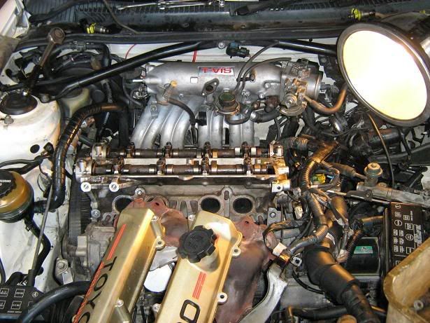
    If you have an early 3sge head (mine was 1985, one of the very first), if you compare it to your early 90's 5sfe block (mine was 1990), you will notice the oil passages at either corner, and all the coolant passages match. Make sure you clean the surface of the block and remove all the old gasket and grime. A wire brush on a drill works well. It will not damage the block as it is cast iron. With the head already assembled, Cams on and torqued up appropriately (make sure u follow the torquing sequence described in your repair manual) Put the 3sge head gasket on the block. Although the 3sge head gasket is made for an engine with a slightly smaller bore, the piston will not go any further up than the top of the block and wont' cause a problem to it. The bore size difference is very small anyways, and the head gasket should be lined with metal around each cylinder for any extra strength for the very small, insignificant amount of head gasket that is exposed. The boys at the workshop and I were insistant on using a 3sge head gasket rather than a 5sfe as the 3sge head gasket lets the block coolant passages flow better. compare the old 5sfe head gasket to the 3sge and you will see how much more open the openings for the coolant passages are on the 3sge. This is a peformance head and by being so, you would assume it would require more cooling for the higher temperatures its exposed to and therefore you wouldn't want to do anything to inhibit any possible extra water flow. Hence use the 3sge head gasket. These heads are soft and can warp, bend and distort. Heat exposure can cause damages like this.

    Following your service manual, bolt down the head and torque up the head bolts appropriately using your torque wrench in the proper sequence. slide on your tvis butterlies on the intake side, making sure you have already cleaned the mating surfaces and put in a fresh gasket from the VRS set. Fit the intake manifold, again with the gasket. Heres the painful part, fit the nuts onto the intake manifold studs to fasten the intake manifold and tvis butterflies in place. you will be skinning your knuckles and accomplishing the near impossible to fit the nuts and torque them up. it is applicable, but you might have to feel around blindly, or access them via under the vehicle. It was considered before putting the head down onto the block to bolt up the manifold first for ease, but the manifold and head together proved to be an obstruction to bolting the head down.

    The 3sge has an oil sender mounted on the side of the head. The 5sfe wiring loom will accomodate for this, but its useless as it doesn't send the right signals. Keep it there if you want for the time being so that oil doesn't spill out. However your car will keep showing an oil warning light cause the oil sender does not send off the right signals. Go to the wreckers or remove from your original head the big round 'oil switch' (as the toyota lads call it, cause its not for a guage and therefore not an oil sender). The diameter of the oil switch might be too big or small to bolt straight into the head where the 3sge oil sender goes. If not the right size, take both your oil sender and oil switch to your auto parts store and buy some form of thread adapter.

    Following the service manual, fit your timing belt and tensioner, making sure its in proper timing. If you have a 3sge oil pump pulley, you will notice the number of teeth is different. the 5sfe one has less, meaning it will turn more per number of teeth than the 3sge. This is good! this is an increase in oil pressure (without blowing seals thankfully). You may also notice that ur timing of the cams might not mesh up right with the crank and the timing belt. It may result in either being half a tooth retarded or half a tooth advanced. Go half a tooth advanced, otherwise she will be very sluggish. Your 3sge timing belt covers should now be in place, they should bolt straight up. Your engine mount on the timing belt side should be back on now as well as the harmonic balancer etc. All is left is the vacuum lines, coolant lines, distributor, exhaust manifold, coolant outlet, alternator and powersteering etc.

    --------------------------------------------------------------------------

    E) VACUUM AND RADIATOR HOSE PLUMBING:


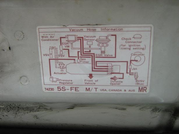
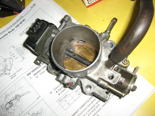
    Have a print out from google images or your celica workshop manual of the vacuum and cooling system diagrams. All vacuum fittings for the 5sfe NEED to be replicated as much as possible, EXCEPT the emissions components. The EGR valve, the fitting it has for the exhaust gas to recirculate into the manifold can just be blocked off with silicone. (This was done on mine as i did not have the exhaust recirculation line fitting on my exhaust manifold. This is only present on early 3sge heads, the later 3sge heads of the st162's and onwards have an exhaust recirculation fitting on the head itself.) its up to you, but its not needed. I don't have smoke pouring out of my exhaust nor foul smells from blocking off the emissions gear. The throttle body will have 3 small vacuum lines on top. 2 in the manifold direction, and one towards the air cleaner direction. Add a bit of hose to the one in the air cleaner direction and block off with a bolt. As long as your manifold pressure regulator (including its VSV) is all vacuum plumbed right, along with your brake booster and you MAP sensor, and the your set. You might as well use up the left over vacuum fittings on the manifold by plugging up the EGR valve and vacuum modulator. Any excessive vacuum lines or fittings left over should be examined as to where they belong. If they are no longer needed, they can be blocked off. I had 1 vacuum fitting in the manifold left over, and i just blocked it off. I also had to vacuum lines coming from under the car, from memory they may have been more emissions stuff, but they were then blocked off too. You may have to buy some more vacuum hose to plumb a line from the manifold to the MAP sensor, i just used some left over that i had.

    As long as your MAP sensor, Manifold pressure regulator, BIG ISC vacuum fitting and brake booster is plumbed up, the car should be set. But if there are excess lines and fittings left, make sure they are blocked to prevent any vacuum leaks into the manifold. Regardless of the ones just mentioned, try your best to fit at much of the original 5sfe vacuum stuff as possible.

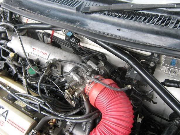
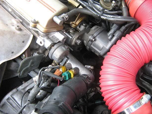
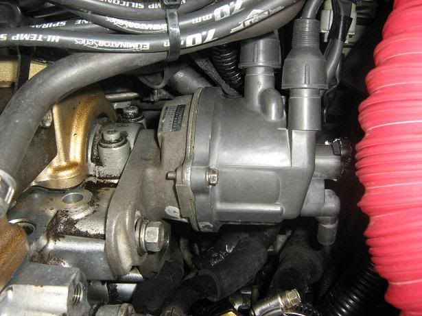
    There is enough fittings on the 3sge water outlet to satisfy the original cooling system of the 5sfe (including heater). Connect up all the heater hoses, including heater return hoses. Just go along on your cooling system diagrams checking out each one. Make sure that the 3sge throttle body has the appropriate water lines going into the base of it (for the thermostat based ISC for your cold starts). There should be 3, and one massive vacuum fitting that goes into the 3sge manifold. There will also be a small vacuum line, just block off with silicone. The 3 water hose fittings that are appropriate to the 3sge throttle body ISC have coolant lines ready to be used left over from the original 5sfe setup, and are therefore sitting around in your engine bay and have to be connected up. Just use your 3sge cooling diagrams to work out where you see fit as to where they go. These 3 water lines need to be connected to the ISC to complete the coolant flow circuit.

    The ISC: (Notice the 3 small water hoses & the little vacuum line. You Can not see the large vacuum line leading into the manifold as it is on the other side)


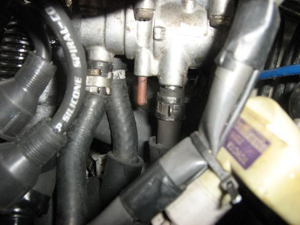
    Check all your hoses and plumbing while you are doing this procedure for cracks and frays. Vacuum leaks into the manifold are a pain in the backside. Use silicone gasket maker or hose clamps anywhere your gut tells you to help seal any piping for the cooling or vacuum lines.

    AND REMEMBER! Use type A green coolant when you refill the radiator, which is not just anti-corrosive, but is also anti-boil and anti-freeze.
    st185 GT4 309 hp 12.4s 1/4 mile 16psi

  3. #3
    Dude with a spanner Grease Monkey bajachris88's Avatar
    Join Date
    Apr 2007
    Location
    QLD
    Posts
    88

    Default Re: TUTORIAL: How to 5s-ge

    --------------------------------------------------------------------------

    F) MISC:

    Put the power steering belt back on. Fit the alternator back on using the 3sge alternator mount, tensioner and belt. The belt will be a firm fit, but it will get on there. tighten up the belt with the tensioner to the point where the belt can't be rotated more than 90 degrees by hand between the A/C compressor and alternator. Make sure the 2 electrical connectors behind the alternator a connected backup. Also make sure the earth line on the alternator mount is connected back to the line on the body (on the fender side). When you put the heat shield cover over the exhaust manifold, get a pair of tin snips as you will have to cut a little off to make it fit around the new alternator mount.

    Do a full check over, make sure nothing is forgotten. Make sure your distributor ignition lines are plugged up correctly from cylinder 1 to 4 in the right firing order, with cylinder one being the closest to the timing belt. Use the 3sge ignition leads for the spark plugs. You will have to use the 5sfe coil lead instead of the 3sge set. The 5sfe end will fit fine into the coil, but you will have to work out a way for it to stay on the gt4 cap. The 5sfe end with the external black clip connector removed should sit in there firmly (if not bend out the metal contact to make it larger and tighter fitting into the distributor cap). If it sits in there firmly, you just want a backup so it doesn't fall out. Selley's gasket maker will seal it in there and prevent water from getting in as well. Just give it time to cure though.

    Make sure the 5sfe wiring loom plugs are all connected up again. This includes your distributor, Throttle position sensor, coolant temperature sensors and MAP sensor.

    Fill your engine with about 4.2 ltrs of 20w50 oil. I think that was the capacity, double check your car workshop manual or owners handbook to make sure it is. Yes 20w50 is a thick oil for a 5sfe. A 5sfe is recommended to have 10w40. But the old 3sge head is recommended to have 20w50. If you use too thin of an oil, like the 10w40 instead of 20w50, your tappets might end up quite noisy. Using a thicker oil is not a bad thing, it actually reduces top end noise and oil leakage. Rev pickup most likely will be affected, but this ain't a bad start. If you experiment with thinner oil, do tell me how you go.

    Eventually, if you don't have to go back to the drawing board with any motor issues, remember to flush your fresh coolant and your fresh oil to remove any debree from the head exchange you have just completed. (IE: old head gasket material etc etc that fell into the coolant and oil passages). Throw in a fresh oil filter too.

    --------------------------------------------------------------------------

    G) FIRST STARTUP:


    Turn your key to the "ON" position, and make sure the centre console shows the normal start up light arrangement. IE: oil light, park brake and the engine light (hopefully not flashing). If the engine light is flashing, something is not connected. Use your workshop manual, put your car in diagnosis mode and find out whats wrong and fix it. Check under the hood to see that your fuel rail and all other fuel related lines aren't leaking. When your key is turned to on, your fuel pump automatically pressurises the system in preparation for you to turn the motor over. If no leaks while in the on position, than you should be sweet.

    Keep a fire extinguisher nearby. They can never go astray incase of the 'God forbid' worst case possibilities. With confidence in your cam timing and your distributor (although you distributor may not be timed properly because the engine hasn't been turned on yet), with the 5sfe signal rotor in the original gt4 signal rotor orientation on the shaft, its a good rough estimate, we might be able to get things cracking.

    If your battery has enough charge, turn her over. If the engine backfires, or kicks back while turning or starts but sounds gutless and just chuggin (not missing though) go to the distributor section and read about setting the ignition timing.

    if you notice the engine not idling at the same consistant speed (IE: reving up and down periodically), that means u need to adjust your throttle position sensor. The throttle position sensor initially had room for adjustable movement for the purposes of tuning. If when redrilling the mount holes for the throttle position sensor you didn't make the holes large enough for adjustment, now is the time you will need to remove the 2 bolts holding it, slide it off and redrill or machine (what ever floats your boat) the holes to be able to move it. Its not hard.

    IF all done properly she should be running fine. Running temperature should be nearly the same, just under halfway on the guage. Keep a close eye to make sure it doesn't overheat or hit the red line on the guage during the initial tests. If its creeps more than 3/4s, shut it off and revise your setup. If you hit the red line all your plastic, vacuum and coolant hoses will start to become brittle and perish. (IE: more work and money and time replacing, let alone the possible damages inside the motor). Make sure it does run at the right temperature and the thermo fan kicks in appropriately. If the thermo fan does not kick in, best off checking your wiring at the water outlet for the water temp sensor (one of them is for the thermo fan).

    --------------------------------------------------------------------------

    H) CONCLUSION:

    Take it for a spin and enjoy. The intake roar is lovely. You will realise the fuel economy isn't as great as it used to be. You also will notice the lower end power is pretty average, but once you pass 3000 rpm the power kicks in and it does not drop. I have only taken it up to 5500rpm so far in my initial trials and the power was still going. They say the 3sge head is good for 9000rpm, but keep within your 5sfe red line to keep your stock pistons and conrods happy. Despite the reduction in compression ratio, there is a gain in HP. I advanced my ignition timing greater than 10 degrees before top dead centre to find it. I couldn't tell you how much advance though because i played it by ear and feel and without a timing light. With the reduced compression ratio, you can advance your ignition further now without the damaging 'pinging'. If you want your HP do advance your ignition timing only a little bit, no more than half an inch for safety. If you hear pinging (rattling noise when the engine is warm and underload), than retard your ignition timing a bit.

    The reduction in compression ratio is a 'power loss' although the resulting motor still is superior than the orginal 5sfe in my opinion after driving the 5sfe for 18 months. This head conversion along with the reduced compression ratio has been prep work for a forced induction setup to come far into the future. Just a mild 10 psi max at the very most though unless i rebuild the engine with different bottom end internals. Although this engine setup in its naturally aspirated state is more fun than the original 5sfe.

    Note: Being able to activate the TVIS to shut the butterfly valves at low revs will help your lower rpm power. You will have a far better lift off. The 3sge TVIS is something your 5sfe ecu can not control, but i am working on a controller that is totally independant of the ecu. The tachometer in the guage console is driven by a current from the ecu (as the ecu gets the RPM from the 24 tooth signal rotor in your dissy {If anyone tells me its from the ignitor they should knock themselves out cause they are wrong in the case of the 5sfe celica}). Using a relay which could piggy back off the current from the tacho, along with variable resistors for adjustable TVIS rev activation, the relay can activate the TVIS butterfly control when the tacho reaches a certain rev.

    TVIS will help your lower end hp and torque curve. If you disagree, than ur crazy. Heres proof: http://www.toyotacelicaonline.com/celica1/TVIS.htm. Sure its old tech, but it helps and makes the driving experience a little more fun.

    Enjoy and tell me how ur 5sge goes.


    Chris Leete.
    st185 GT4 309 hp 12.4s 1/4 mile 16psi

  4. #4
    Junior Member Carport Converter Dale's Avatar
    Join Date
    Sep 2005
    Location
    NSW
    Posts
    1,914

    Default Re: TUTORIAL: How to 5s-ge

    Great write up, can tell you put a lot of effort and research into this project of yours and it's turned out well

    You should be able to go to a 15w/40 oil... it's what gen 1 3sge were meant to run

    rep your way
    I am the sun

  5. #5
    Founding ****** Automotive Encyclopaedia Mos's Avatar
    Join Date
    Jul 2005
    Location
    NSW
    Posts
    1,157

    Default Re: TUTORIAL: How to 5s-ge

    Looking good

    Some questions/suggestions:

    Quote Originally Posted by bajachris88
    The tachometer in the guage console is driven by a current from the ecu
    How sure are you of this?
    I haven't seen a single toyota tach that's controlled by a current from the ecu - they all run off a frequency (ie the information for the tach is "encoded" into a frequency, not a current).

    Quote Originally Posted by bajachris88
    (as the ecu gets the RPM from the 24 tooth signal rotor in your dissy {If anyone tells me its from the ignitor they should knock themselves out cause they are wrong in the case of the 5sfe celica}).
    How sure are you of this also?
    Generally the tacho signal comes from the ignitor. Ie it goes something like this: 24 tooth sensor -> ECU -> ignitor -> tacho.
    Generally only coilpack ECUs supply the tacho signal directly.
    In an ST185 the tacho signal comes off the ignitor, and while I haven't worked on an ST184 it would shock me to find this different.
    Which pin on the ECU is the tacho output?

    Quote Originally Posted by bajachris88
    Using a relay which could piggy back off the current from the tacho, along with variable resistors for adjustable TVIS rev activation, the relay can activate the TVIS butterfly control when the tacho reaches a certain rev.
    You could use the LM2917 chip - http://www.national.com/mpf/LM/LM2917.html - it is a frequency to voltage converter, with a built in comparator, so you can build an adjustable rpm switch with few components. Available from Jaycar for $6.95 - ZL3930.
    Page 8 of the pdf datasheet http://www.national.com/ds/LM/LM2907.pdf has such an example.

    Mos.
    Admin, I.T., Founding Member, Toymods Car Club Inc.
    2000 IS200 Sports Luxury 1UZ-FE VVTi, 1991 MX83 Grande 2JZ-GTE (sold)

  6. #6
    Dude with a spanner Grease Monkey bajachris88's Avatar
    Join Date
    Apr 2007
    Location
    QLD
    Posts
    88

    Default Re: TUTORIAL: How to 5s-ge

    woah! this is oldskool. going back a few moons now.

    If anyone wanting an update, a lad in Canada just finished his 5sge heavily based on this tutorial, cept he eliminated the tvis system altogether. hes runnign the stock computer and loving it.

    Mine had a soft head that seemed to be a problem from word go. I blame the experimentation on the dissies that caused the exhaust manifold to glow red hot before i found the right solution.

    Mos all ur observations were correct. Its been a steap learning curve since 2008 lol.

    I would build this engine again, but would consider larger comp ratio if not forced ducted as the low down power is ordinary. all the fun is from 4000 rpm onwards and it was fun. On that note, beefed up conrods of any sort that can get ya into the 9000 rpm red line would be sick as and a pro tuned piggy back would make things very comfortable. good clutch and lightened flywheel to rev quick and launch/slip higher in the revs on take off would help with comfortability as well. Just for 'street' friendlyness. Like... low down it has heaps of torque, but slightly sluggish for pickup until the revs build.

    Bigger injectors and all that jazz aren't required, the Canadian lad was having flooding issues when he upgraded. its definitely a good 'bang for buck' without any requirement to remove the engine itself out of the bay.

    Chris.
    st185 GT4 309 hp 12.4s 1/4 mile 16psi

  7. #7
    Junior Member Carport Converter StuC's Avatar
    Join Date
    Oct 2005
    Location
    Victoria
    Posts
    1,792

    Default Re: TUTORIAL: How to 5s-ge

    im pretty sure TVIS is vacuum operated only on the 162s. Its eben a while since actually playing with st162s and TVIS though.

  8. #8
    Dude with a spanner Grease Monkey bajachris88's Avatar
    Join Date
    Apr 2007
    Location
    QLD
    Posts
    88

    Default Re: TUTORIAL: How to build a 'cheap' 5S-GE motor from 5S-FE

    Yes TVIS is vacuum operated with an electric solenoid to trigger it off.

    The Canadian guy took the TVIS butterflies out as he saw them posing a restriction to the intake flow, so he removed the system all together (rather than just unplugging the vacuum canister)

    If u want TVIS still, just fit it as per stock method, plumb up the canisters and for the 5sfe stock ecu, u will need to purchase a frequency switch kit (like $30) that triggers a relay to 'open' when a certain rev range has been reached. (its all adjustable). You will use this to activate ur tvis when the 5sfe ecu is unable to (as its not programmed for tvis).
    st185 GT4 309 hp 12.4s 1/4 mile 16psi

  9. #9
    Junior Member Carport Converter StuC's Avatar
    Join Date
    Oct 2005
    Location
    Victoria
    Posts
    1,792

    Default Re: TUTORIAL: How to build a 'cheap' 5S-GE motor from 5S-FE

    gotcha. I didnt realise it was solenoid switched. I always thought it was purely vacuum. Oh well.

  10. #10
    Dude with a spanner Grease Monkey bajachris88's Avatar
    Join Date
    Apr 2007
    Location
    QLD
    Posts
    88

    Default Re: TUTORIAL: How to build a 'cheap' 5S-GE motor from 5S-FE

    ur all good mate, yea it only turns on when a certain rpm range is hit.

    its only on or off... not 'gradual', and only triggers when that programmed rpm is reached.
    st185 GT4 309 hp 12.4s 1/4 mile 16psi

Similar Threads

  1. Guide: How to build a K series motor
    By oldcorollas in forum Tech and Conversions
    Replies: 78
    Last Post: 19-10-2007, 08:43 PM
  2. Guide: How to build a K series motor
    By oldcorollas in forum FAQ
    Replies: 1
    Last Post: 26-09-2005, 07:51 PM

Bookmarks

Posting Permissions

  • You may not post new threads
  • You may not post replies
  • You may not post attachments
  • You may not edit your posts
  •